

In industrial fluid transfer, measurement accuracy directly impacts operational profitability. Whether you are operating a chemical processing plant in Europe, an offshore rig in the Middle East, or a manufacturing facility in one of Gujarat's bustling GIDC (Gujarat Industrial Development Corporation) estates, inaccurate fuel measurement leads to inventory discrepancies, inefficient batching, and financial losses. When Fuel Flow Meters begin displaying fluctuating readings, wrong totals, or display errors, plant managers and industrial engineers must act swiftly to diagnose and correct the underlying fault.
The cost of unexpected downtime on a critical diesel or lamp fuel transfer line can be severe. However, blindly replacing flow measurement equipment without understanding the root cause of the failure is an expensive and often unnecessary approach. Modern digital turbine meters are highly robust, and most measurement errors stem from fluid dynamics, improper installation, or minor mechanical obstructions rather than catastrophic failure. This guide provides a comprehensive framework for Fuel Flow Meters troubleshooting, allowing maintenance teams to perform fast diagnostics, execute clear corrective actions, and restore reliable measurement to industrial transfer lines.
Supported by the Make in India initiative, manufacturers like Lumen Instruments produce export-quality measurement devices that comply with stringent global standards (ISO, CE) and domestic BIS standards. By understanding how to maintain and troubleshoot these precision devices, procurement heads and engineers can ensure long-term accuracy and maximize the lifespan of their capital equipment.
1. Quick Reference: How Fuel Flow Meters Works
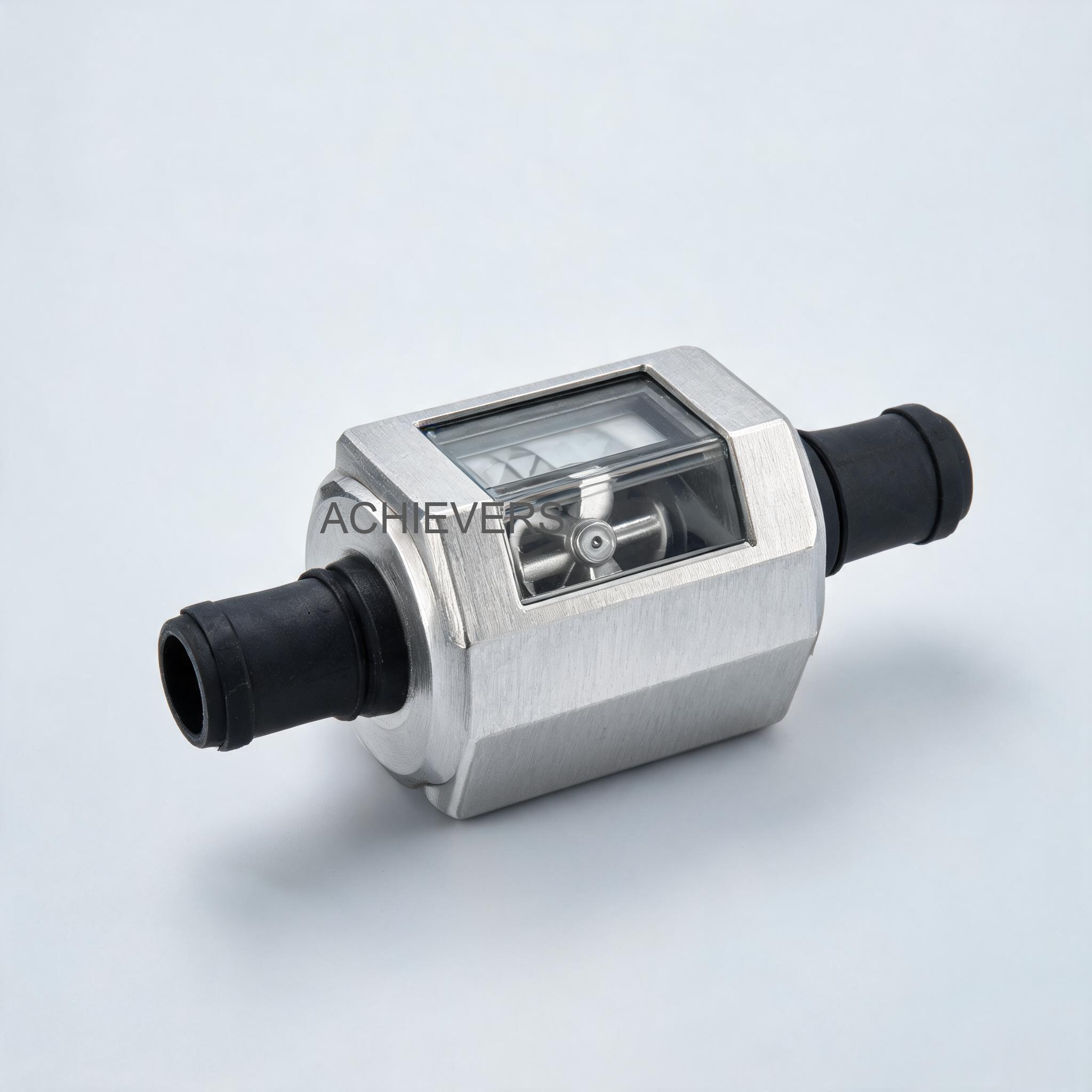
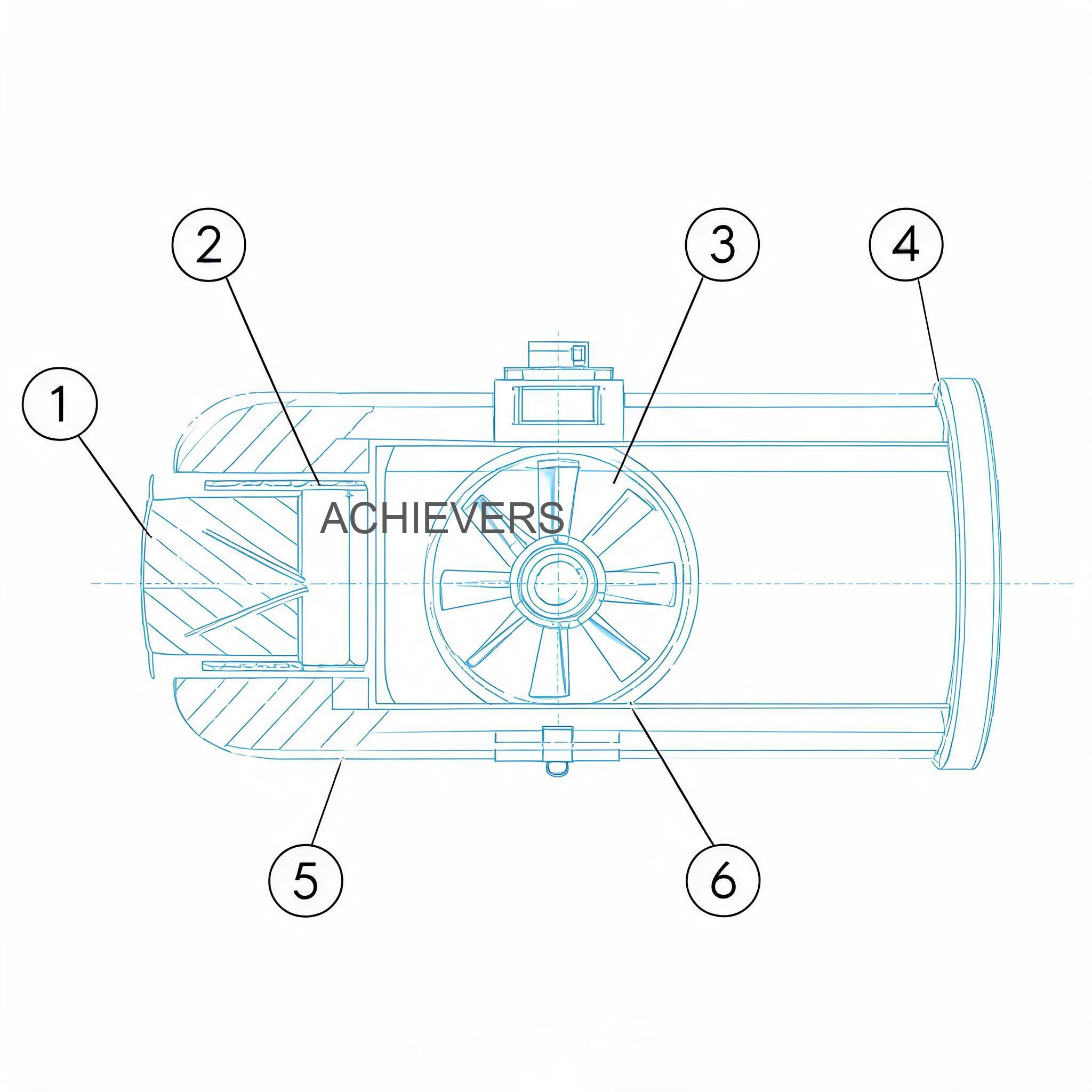
Before attempting any field repairs, it is critical to understand the operating principles of the Fuel Flow Meters utilized in your facility. The standard model features a precision Turbine Measuring System designed for the transfer of diesel fuel, lamp fuel, and compatible low-viscosity fluids.
When fluid enters the meter housing—typically an anodized aluminum body built to withstand harsh industrial environments—it passes through a set of internal flow deflectors. These deflectors condition the fluid stream, directing it against the blades of a freely suspended turbine rotor. The kinetic energy of the flowing fluid forces the turbine to spin at a velocity directly proportional to the flow rate.
A magnetic pickup sensor detects the rotational speed of the turbine blades. This raw rotational data is processed by the internal microprocessor and converted into volumetric units. The results are displayed on a high-contrast Five-Digit Readout with a Resettable Totalizer. The unit is capable of measuring in Gallons, Liters, Quarts, and Pints, making it highly versatile for global applications.
Key Technical Specifications for Troubleshooting Reference:
- Operating Range: 11 to 98 LPM (Liters Per Minute)
- Maximum Pressure: 50 psi (3.4 bar)
- Accuracy: +/- 1% Accuracy
- Connections: 1 in. Inlet and Outlet (Reduces down to 3/4 in. using a reducer bushing)
- Housing: Anodized Aluminum
- Installation: In Line or at the End of the Delivery Hose
In Simple Terms
Think of a turbine flow meter like a windmill inside a pipe. As fuel flows through the pipe, it pushes the blades of the windmill, causing it to spin. A small computer inside the meter counts how many times the windmill spins and calculates exactly how much liquid has passed through. If the pipe is partially blocked, if there is air in the liquid, or if the flow is too slow to spin the blades properly, the "windmill" spins at the wrong speed, resulting in an inaccurate reading on the digital screen.
2. Troubleshooting Matrix
When a fault occurs, rapid identification of the symptom allows for targeted diagnostics. The following matrix details the most common issues encountered during fuel flow meters troubleshooting, their likely causes, and the required field fixes.
| Symptom | Likely Cause | Diagnosis Steps | Fix |
| — | — | — | — |
| Zero Reading on LCD | Dead battery or loose internal connection | Check the digital display for fading. Open the faceplate to inspect the battery terminals and wire harness. | Replace the battery pack. Reseat the internal ribbon cables to the 5-digit LCD readout. |
| Fluctuating Flow Rate | Air entrainment in the fluid line | Inspect upstream piping and suction lines of the Fuel Transfer Pumps for leaks where air can enter. | Tighten all upstream flanges. Install an air eliminator before the meter inlet. |
| Wrong Totalizer Reading | Operation outside the 11-98 LPM range | Measure the actual flow rate using a bucket test and a stopwatch. Compare against the meter's specification. | Adjust pump speed or valve throttling to maintain a flow rate strictly between 11 and 98 LPM. |
| Meter Consistently Under-Reads | Debris or scaling on the turbine blades | Isolate the line. Remove the meter and inspect the internal turbine rotor for sticky residue or solid particulates. | Soak the turbine assembly in a mild solvent. Gently brush the blades clean. Install an upstream inline strainer. |
| Erratic Display Digits | Heavy vibration from adjacent equipment | Check the mounting stability of the pipeline. Feel for excessive vibration transferring to the meter body. | Relocate the meter to a stable section of pipe or install flexible vibration-damping hoses on either side. |
| Fluid Leaks at Connections | Improper seating of the reducer bushing | Inspect the 1 in. to 3/4 in. reducer bushing. Check for damaged threads or missing thread sealant. | Remove the bushing, clean the threads, apply industrial-grade PTFE tape or liquid thread sealant, and re-torque to spec. |
| Whining Noise During Operation | Cavitation or worn rotor bearings | Check the system pressure gauge. Ensure the pressure drop across the meter is not causing the fluid to vaporize. | Increase backpressure to prevent cavitation, or replace the turbine rotor bearings if wear is detected. |
| Display Fades in High Heat | Direct exposure to extreme ambient temperatures | Measure the surface temperature of the anodized aluminum housing. Check if the display faces direct sunlight. | Install a sunshade over the meter. Ensure operating temperatures remain within the LCD's specified thermal limits. |
| Measurement Drift Over Time | Shift in fluid viscosity or specific gravity | Check if the product being metered has changed (e.g., switching from standard diesel to heavy lamp fuel) or if seasonal temperatures have shifted drastically. | Recalibrate the meter using the new fluid at the current operating temperature to restore the +/- 1% accuracy. |
| Turbine Completely Stuck | Large solid obstruction | Perform a bypass test. If fluid flows but the totalizer does not increment, the rotor is physically jammed. | Disassemble the meter housing. Remove the foreign object (e.g., welding slag, pipe tape). Reassemble and test. |
3. Step-by-Step Field Diagnosis Procedure
When erratic totals or display errors occur, follow this standard operating procedure to isolate the fault safely and efficiently.
Required Tools: Adjustable wrench set, Phillips and flathead screwdrivers, multimeter, clean calibration bucket (minimum 20-liter capacity), stopwatch, non-corrosive cleaning solvent, and safety gear (gloves, safety glasses).
Step 1: Isolate the Metering Line
Before breaking any fluid connections, shut off the power to the primary transfer pumps. Close the upstream and downstream isolation valves. Ensure that the line pressure is fully relieved to 0 psi to prevent hazardous fuel spray.
Step 2: Inspect the Digital LCD and Power Supply
Check the five-digit readout. If the screen is blank or the numbers are missing segments, open the electronic housing. Test the battery voltage using a multimeter. If the voltage is below the operational threshold, replace the battery. Clean the battery contacts to ensure a solid electrical connection.
Step 3: Verify Flow Parameters and Pressure Restrictions
Consult your system's pressure gauges. Ensure the operating pressure does not exceed the meter's maximum rating of 50 psi (3.4 bar). Furthermore, calculate your typical delivery speed. The turbine measuring system requires a minimum flow of 11 LPM to accurately spin the rotor, and a maximum of 98 LPM to prevent over-speeding and bearing damage.
Step 4: Check External Connections and Reducer Bushings
Inspect the 1-inch inlet and outlet ports. If you are utilizing the reducer bushing to step down to a 3/4-inch connection, verify that the bushing is correctly aligned and not causing a physical bottleneck. Look for weeping fuel around the threads, which indicates a pressure leak that could skew totalizer readings.
Step 5: Extract and Inspect the Turbine Rotor
Carefully separate the meter body. Extract the turbine measuring mechanism. Examine the anodized aluminum housing for scoring or impact marks. Spin the turbine with your finger; it should rotate freely with minimal resistance. If it feels gritty or sluggish, dirt or waxy fuel residues have fouled the bearings.
Step 6: Clean and Reassemble
Submerge the turbine assembly in a clean, compatible solvent. Use a soft-bristled brush to remove any particulate matter from the rotor blades. Do not use compressed air to spin the turbine while dry, as this will destroy the bearings. Reinsert the mechanism into the housing, ensuring flow direction arrows align correctly with the pipeline.
Step 7: Purge the Line of Entrained Air
Reopen the isolation valves slightly to allow fuel to enter the meter slowly. Purge all air from the system. Air bubbles passing through a turbine meter take up volume but contain negligible liquid mass, causing the meter to artificially inflate the totalizer reading (over-registering).
Step 8: Perform a Field Calibration Check
Dispense a continuous flow of fluid into a certified calibration bucket. For an accurate test, dispense at least 20 liters. Compare the physical volume in the bucket to the reading on the meter's LCD. If the variance exceeds the stated +/- 1% accuracy, utilize the meter's internal software calibration sequence to adjust the K-factor until the digital readout matches the known physical volume.
4. Installation and Setup Errors That Cause Ongoing Problems
A significant percentage of fuel flow meter fluctuating readings causes and fixes can be traced back to the initial setup phase. Even the highest-quality industrial instruments will fail to deliver reliable data if fundamental fluid dynamic principles are ignored during installation.
| Installation Error | Symptom / Resulting Problem | Corrective Action |
| — | — | — |
| Insufficient Straight Pipe Run | Erratic readings due to turbulent, swirling fluid hitting the turbine blades. | Provide a straight, unobstructed pipe run of at least 10x the pipe diameter upstream, and 5x downstream of the meter. |
| Installing Backwards | Zero flow registration or severe pressure drops. | Check the flow direction arrow stamped on the anodized aluminum body. Reinstall to match fluid flow. |
| Oversized Pumping Systems | Cavitation, excessive noise, and rapid destruction of turbine bearings. | Ensure pump output does not exceed the 98 LPM threshold. Install a bypass valve if pump output is too high. |
| Lack of Upstream Filtration | Turbine jams frequently or blades suffer physical damage from debris. | Install a Y-strainer (typically 40 to 60 mesh) immediately upstream of the straight pipe run. |
| Vapor Pockets in Hose-End Setup | Meter over-registers volume when installed at the end of an empty delivery hose. | Keep the delivery hose packed with fluid, or utilize a non-return (check) valve to prevent the hose from draining. |
| Improper Grounding | Electrical noise causing the digital display to freeze or record phantom flow. | Ensure the piping system and meter body are properly bonded and grounded according to facility electrical safety codes. |
5. Preventive Maintenance to Avoid Recurrence
Maintaining industrial fuel flow meter calibration and accuracy requires a proactive approach. Implementing a standardized preventive maintenance (PM) schedule ensures that the equipment continues to perform reliably, minimizing sudden breakdowns and safeguarding inventory data.
For routine maintenance, operators should conduct daily visual inspections for leaks around the 1-inch inlet and outlet connections and check the digital display for clarity. Weekly tasks should include verifying that the resettable totalizer clears properly and checking the flow rate against the 11 – 98 LPM operating envelope. On a monthly or quarterly basis, depending on the volume of fuel transferred, maintenance teams should isolate the meter, remove the internal turbine system, and clean it thoroughly to remove fuel varnishes or microscopic particulate buildup.
Procurement and Export Pricing Context:
For plant managers assessing total cost of ownership, maintaining these meters is highly cost-effective compared to full system replacement. As a benchmark, the typical Indian market price range for high-quality, export-ready digital turbine fuel meters of this specification generally falls between Rs. 5,000 and Rs. 15,000, depending on precise material grades, certifications, and order volumes. When factoring in the standard 18% GST (Goods and Services Tax) for domestic Indian purchases, businesses operating in industrial sectors such as power generation, mining, or chemical processing can easily budget for spare units. Under the Make in India initiative, local manufacturers provide these robust, precisely engineered devices at highly competitive price points, matching the quality of more expensive European or North American imports while ensuring rapid availability of replacement parts across GIDC zones and international export markets.
Regular calibration checks are the most critical aspect of preventive maintenance. Variations in fuel temperature alter the fluid's viscosity, which can subtly shift the turbine's rotational dynamics. A meter calibrated during the freezing temperatures of winter may read slightly differently during the intense 45°C+ heat of an Indian summer or Middle Eastern afternoon. Performing a volumetric bucket test at the start of each season ensures that the +/- 1% accuracy is strictly maintained.

6. When to Call Service vs. Fix Yourself
One of the primary benefits of the turbine measuring system is its mechanical simplicity, which allows for extensive field repairs. Industrial engineers and trained maintenance personnel can safely handle battery replacements, screen cleanings, turbine rotor extractions, debris removal, and software recalibration.
However, there are specific scenarios where field repair is not viable and factory service is required. If the anodized aluminum body suffers a severe impact that deforms the internal measuring chamber, the meter must be replaced, as precise internal tolerances are destroyed. Similarly, if the digital circuit board sustains water ingress or a high-voltage short circuit resulting in a burned PCB, field soldering is not recommended. Lumen Instruments provides a comprehensive One-Year Warranty on their meters; attempting to reverse-engineer or modify the core electronic potting within the warranty period may void coverage. If a meter exhibits persistent, unexplainable drift even after a thorough cleaning and recalibration, it is advisable to contact the supplier in India for a diagnostic evaluation or a replacement unit.
FAQ
Q: Why does my digital fuel flow meter show a wrong totalizer reading even when the flow rate seems normal?
A: This is usually caused by air entrainment in the fluid lines or operating below the minimum 11 LPM threshold. Air bubbles spin the turbine without delivering actual liquid volume, and excessively slow flow allows liquid to slip past the blades without registering accurately.
Q: How frequently should industrial fuel flow meter calibration and accuracy checks be performed?
A: In heavy industrial environments or high-volume commercial transfer applications, calibration should be verified every 3 to 6 months. Additionally, recalibrate whenever you switch to a fuel with a different viscosity or experience drastic seasonal temperature changes.
Q: Can this meter be used with highly corrosive chemicals or water?
A: The standard unit is constructed with an anodized aluminum body designed specifically for petroleum-based products like diesel and lamp fuel. Using it with highly corrosive chemicals or deionized water may cause rapid oxidation or galvanic corrosion of the internal components.
Q: What is the benefit of installing the meter inline versus at the end of the delivery hose?
A: Inline installation typically provides a more stable, vibration-free environment with proper straight pipe runs, leading to maximum accuracy. Hose-end installation offers greater operational convenience for operators dispensing fuel directly into vehicles or machinery, such as with a Mobile Diesel Dispenser, though it requires careful handling to avoid dropping the digital display.
Q: The digital display is completely blank. Is the meter broken?
A: Most likely, the internal battery has simply depleted. The five-digit LCD readout operates on an independent battery system to preserve the resettable totalizer data. Replacing the battery usually restores full functionality instantly.
Q: My facility operates in extreme heat. Will this damage the meter?
A: While the anodized aluminum body is highly durable, direct, prolonged exposure to extreme UV and high ambient temperatures (common in regions like Gujarat or the Middle East) can cause the LCD screen to blacken or fade. It is recommended to install a simple physical sunshade over the display if mounted outdoors.
Q: What should I do if the turbine is making a loud whining noise?
A: A high-pitched whine indicates that the turbine is either over-speeding (flow rate exceeds 98 LPM) or that the rotor bearings are worn out. Immediately throttle back the flow rate. If the noise persists, the bearings require replacement.
To ensure your fluid transfer systems operate at peak efficiency with zero measurement discrepancies, trust the precision engineering of Lumen Instruments. Whether you require troubleshooting support, a system upgrade, or wish to inquire about bulk export pricing, contact our technical team today with your required flow capacity, application details, and site conditions for a customized solution.