
For industrial facilities, petrochemical plants, and large-scale manufacturing units, accurate fluid measurement is the backbone of operational efficiency. When transferring high-value fluids like diesel and kerosene, even a minor drift in measurement accuracy can result in massive financial discrepancies over an annual quarter. This is where high-quality Fuel Flow Meters become indispensable. However, installing a top-tier measurement device is only the first step. Without a rigorous, globally recognized preventive maintenance schedule, turbine-based meters can suffer from particulate buildup, calibration drift, and premature mechanical wear. The cost of unplanned downtime and inaccurate fluid dispensation far outweighs the minimal time investment required for routine maintenance.
Operating within strict industrial tolerances requires a comprehensive understanding of your equipment. A proactive maintenance approach ensures that your metering systems maintain their specified +/- 1% accuracy, maximize throughput within the 11 to 98 LPM range, and extend the lifespan of the internal turbine measuring system. Whether you are managing an offshore drilling rig, a remote mining site, or an expansive manufacturing plant, adhering to systematic preventive maintenance protocols reduces the total cost of ownership and ensures compliance with stringent internal and external auditing standards.
1. Product Overview and Critical Wear Components
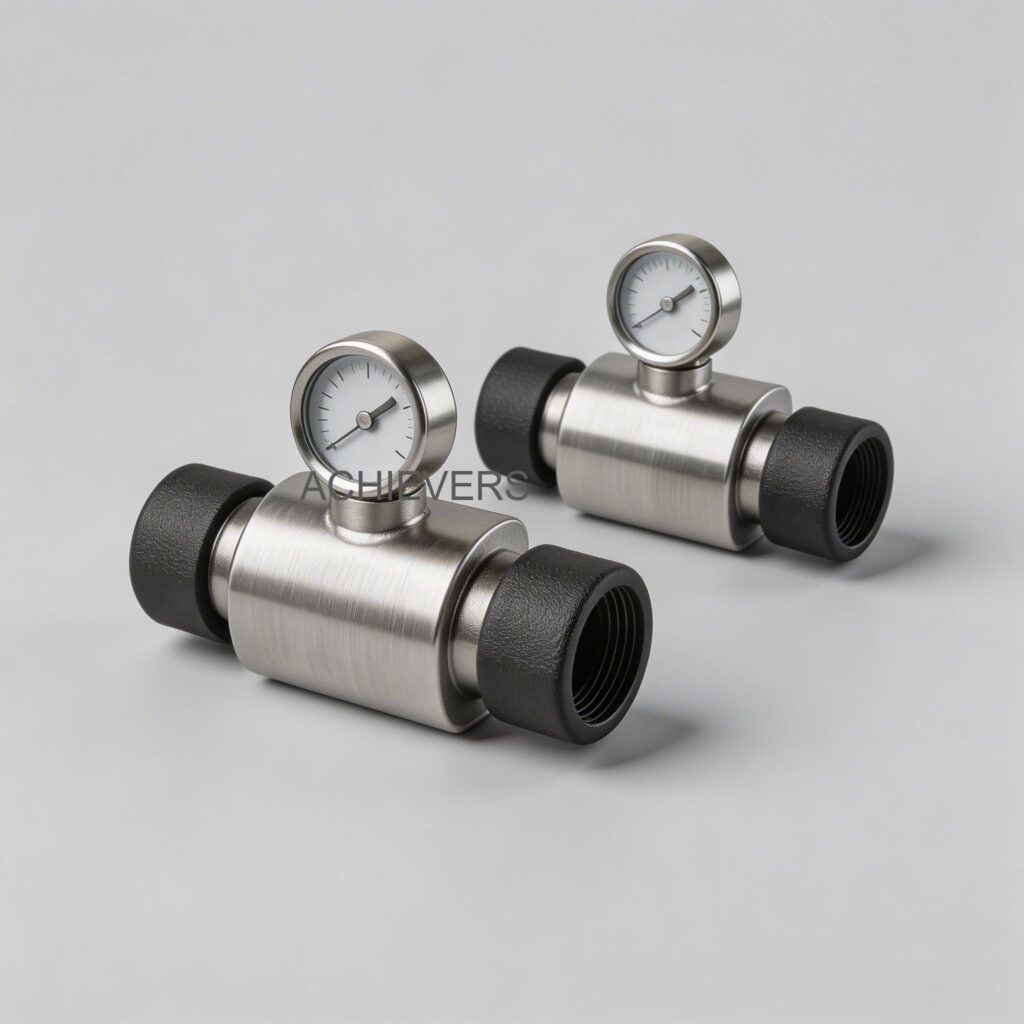
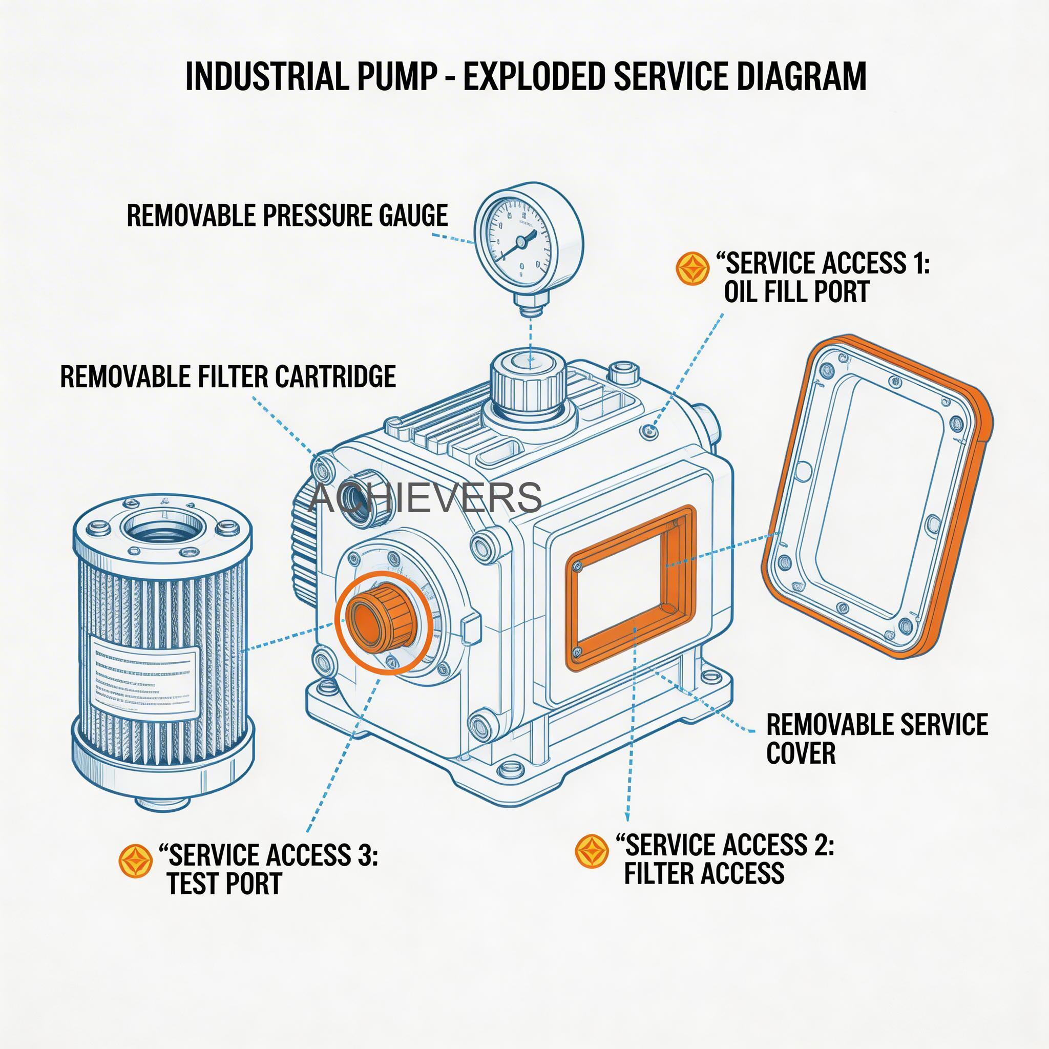
To properly maintain any industrial equipment, plant managers must first understand its mechanical and electronic architecture. Advanced Fuel Flow Meters operate using a highly precise turbine measuring system. As diesel or kerosene enters the 1-inch inlet, the fluid's velocity turns an internal bladed rotor. The rotational speed of this rotor is directly proportional to the fluid flow rate. A magnetic pickup senses the passing of each rotor blade, translating these mechanical movements into electronic pulses that are displayed on the five-digit LCD readout.
The housing of these meters is constructed from high-grade anodized aluminum. This material choice is critical; anodization creates a robust, corrosion-resistant oxide layer that withstands the harsh chemical environments typical in fuel transfer applications. Despite this durable construction, the system operates under continuous mechanical stress and fluid pressures up to 50 psi (3.4 bar). Consequently, specific internal components are subject to natural wear and tear and require routine inspection.
The primary wear components include the turbine rotor assembly, the internal bearings that support the rotor, and the sealing mechanisms. Debris, rust flakes from old storage tanks, or suspended particulates in unrefined fuels can act as abrasives, slowly eroding the sharp edges of the turbine blades. This erosion alters the fluid dynamics inside the chamber, leading to calibration drift. Additionally, the meter utilizes reducer bushings to step down the 1-inch inlet and outlet to a 3/4-inch connection when required. The threads on these bushings, along with their corresponding O-rings, are critical sealing points that can degrade over time due to pressure fluctuations and thermal expansion.
In Simple Terms:
Think of your turbine flow meter like the speedometer in your car, but for liquids. The faster the fuel flows, the faster the internal wheel spins, and the screen calculates the volume. If dirt clogs the wheel, it spins slower than it should, "short-changing" your readings. Preventive maintenance is simply opening it up, cleaning the wheel, and ensuring nothing is blocking the flow, so every single drop of expensive diesel is accurately counted.

2. Preventive Maintenance Schedule
Implementing a standardized preventive maintenance (PM) schedule transforms reactive firefighting into predictable, manageable operations. For Fuel Flow Meters, tasks should be categorized by frequency, ensuring that daily operational checks do not bottleneck production, while comprehensive annual calibrations guarantee long-term accuracy.
Below is a mandatory maintenance matrix designed for facilities operating continuously or in demanding environments.
| Task | Frequency | Responsible | Est. Time | Notes |
| — | — | — | — | — |
| Visual Housing & Leak Inspection | Daily | Machine Operator | 5 Mins | Check for external damage, cracks, or minor weeping at the 1-inch and 3/4-inch reducer bushing joints. |
| Digital Display Readability Check | Daily | Machine Operator | 2 Mins | Ensure the five-digit LCD is clear, responsive, and the resettable totalizer clears to zero without lag. |
| Upstream Strainer/Filter Purge | Weekly | Maintenance Tech | 15 Mins | Clean the pre-filter to prevent particulate matter from reaching the delicate turbine measuring system. |
| Flow Rate Verification (Bucket Test) | Monthly | QA/QC Inspector | 30 Mins | Dispense a known volume into a certified proving can to quickly verify if the meter remains within the +/- 1% accuracy tolerance. |
| Battery Voltage Inspection | Bi-Annually | Maintenance Tech | 10 Mins | Check the voltage of the internal battery powering the LCD. Replace if dimming occurs in varying temperatures. |
| Thread & Seal Integrity Check | Bi-Annually | Maintenance Tech | 20 Mins | Inspect the anodized aluminum threads and PTFE/O-ring seals for signs of chemical degradation or cross-threading. |
| Turbine Rotor & Chamber Cleaning | Annually | Plant Engineer | 45 Mins | Remove the meter from the line, extract the turbine assembly, and clean with approved industrial solvents. |
| Complete Recalibration | Annually | Certified Metrologist | 1 Hour | Perform a multi-point calibration across the full 11 – 98 LPM flow range using traceable reference standards. |
| Reducer Bushing Replacement | Every 2 Years | Maintenance Tech | 15 Mins | Proactively replace the 1 in. to 3/4 in. reducer bushings to prevent metal fatigue and ensure perfect alignment. |
| Complete Assembly Overhaul | Every 3-5 Years | Plant Engineer | 2 Hours | Replace all internal bearings, the turbine rotor, and seals, essentially resetting the meter to factory conditions. |
Adhering to this table ensures that minor issues, such as a partially clogged strainer causing a pressure drop, are identified before they cause the flow rate to drop below the operational threshold or force the Fuel Transfer Pumps to deadhead and overheat.
3. Step-by-Step Procedures for Key Tasks
Executing maintenance tasks correctly is just as important as performing them on time. Improper reassembly can introduce air leaks, strip the anodized aluminum threads, or misalign the turbine mechanism. The following procedures detail the exact steps required for the two most critical maintenance interventions.
Procedure 1: Upstream Strainer and Filter Cleaning
A flow meter is only as accurate as the cleanliness of the fluid passing through it. The upstream strainer prevents damaging debris from entering the turbine chamber.
- Isolate the System (LOTO): Shut down the main transfer pump. Apply Lockout/Tagout procedures to the pump's electrical supply. Close the upstream and downstream isolation valves to trap the fluid.
- Relieve System Pressure: Safely bleed the trapped line pressure (up to 50 psi) using the system's designated pressure relief valve or bleed screw. Ensure a spill containment tray is positioned beneath the work area.
- Open the Strainer Housing: Using the correct size wrench, carefully unscrew the upstream strainer housing. Do not use pipe wrenches that can gouge the metal.
- Extract the Mesh Filter: Carefully pull out the stainless steel wire mesh strainer. Inspect it immediately for large metal flakes or excessive sludge, which may indicate upstream tank degradation.
- Clean the Filter Element: Wash the mesh thoroughly in a parts washer using clean diesel or a mild, non-corrosive industrial solvent. Use a soft-bristle brush to remove stubborn wax or tar deposits. Never use compressed air on a fragile mesh, as it can widen the pore size.
- Inspect for Damage: Hold the cleaned mesh up to a strong light source. Look for tears, separated seams, or collapsed sections. If any damage is found, discard and replace the strainer element.
- Reinstall with New Seals: Place the cleaned (or new) strainer back into the housing. Always replace the housing O-ring or gasket with a new one to guarantee a leak-proof seal.
- Restore Flow and Test: Hand-tighten the housing, then secure it with a wrench to the manufacturer's specified torque. Remove LOTO, slowly open the upstream valve to prime the line, check for leaks, and then open the downstream valve.
Procedure 2: Turbine Rotor Inspection and Sensor Cleaning
If the meter fails a monthly bucket test, the turbine rotor is the most likely culprit. This procedure restores the core measuring system to optimal condition.
- System Shutdown and Drainage: Follow the LOTO and pressure relief steps outlined in Procedure 1. Place a containment pan under the meter and disconnect the delivery hose.
- Remove the Meter from the Line: Unthread the meter from the pipeline or hose end. If the 1 in. to 3/4 in. reducer bushing is used, take care not to cross-thread the aluminum body during removal.
- Access the Turbine Chamber: Depending on the specific assembly orientation, remove the retaining clips or bolts securing the measurement chamber. Carefully separate the housing halves.
- Extract the Turbine Rotor: Gently slide the turbine rotor assembly out of its bearing supports. Note the orientation of the blades—installing the rotor backward during reassembly will result in zero flow registration.
- Clean the Rotor and Bearings: Submerge the rotor in a clean, compatible solvent. Use a lint-free cloth to wipe the blades. Inspect the blade tips for wear, scoring, or burrs caused by passing debris.
- Clean the Magnetic Pickup: Locate the magnetic sensor housed near the rotor cavity. Wipe away any metallic sludge (ferrous dust) that may have accumulated on the magnet, as this will disrupt the electronic pulse generation to the LCD.
- Perform a Spin Test: While holding the rotor assembly, blow lightly on the blades. The turbine should spin freely and smoothly without any grinding noises or sudden stops, indicating healthy bearings.
- Reassembly and Recalibration: Reinsert the turbine in the correct flow direction. Reassemble the housing using fresh O-rings. Reinstall the meter into the pipeline using appropriate thread sealant. Run a calibration sequence using the resettable totalizer to verify the +/- 1% accuracy is restored.
4. On-Site Spare Parts to Stock
Global supply chains can occasionally experience delays. Relying on just-in-time delivery for critical flow meter components can lead to extended downtime. Establishing a localized, well-managed spare parts inventory guarantees that routine maintenance and unexpected repairs can be executed immediately. For small and medium enterprises, maintaining a smart inventory prevents capital from being tied up in unnecessary parts while covering the most vulnerable components.
For our domestic partners in India, a typical Indian market price range for comprehensive spare kits runs between ₹1,500 to ₹3,500 (GST-inclusive cost), a minor investment compared to the massive losses incurred during unmetered fluid transfer or plant downtime.
| Part | Type | Recommended Qty | When to Replace |
| — | — | — | — |
| O-Ring & Seal Kit | Consumable | 3-5 sets | Annually, or whenever the meter housing is opened. |
| Reducer Bushing (1" to 3/4") | Hardware | 2 units | If threads become stripped, cross-threaded, or heavily corroded. |
| LCD Battery Pack | Electronic | 2 units | Bi-annually, or if the 5-digit readout begins to fade or flicker. |
| Stainless Steel Strainer Mesh | Consumable | 2 units | If the mesh is torn, crushed, or permanently fouled. |
| Turbine Rotor Assembly | Core Component | 1 unit | If blades are eroded, or if the free-spin test fails due to bearing wear. |
| LCD Faceplate / Totalizer Board | Electronic | 1 unit | If the resettable totalizer button fails or the screen cracks. |
Store all elastomeric seals (O-rings) in UV-protected, airtight containers to prevent dry rot. Electronic boards and batteries should be kept in climate-controlled environments away from extreme heat and humidity.
5. Diagnosing Maintenance-Related Failures
Even with a robust preventive maintenance schedule, abnormal operating conditions or human error can trigger system failures. The ability to rapidly diagnose these issues minimizes disruption. The table below links common failure symptoms to the specific maintenance tasks that may have been overlooked, providing immediate corrective actions.
| Failure Symptom | Missed Maintenance Task | Corrective Action |
| — | — | — |
| LCD Screen is Blank or Fading | Bi-Annual Battery Voltage Inspection | Open the display housing and replace the internal battery; check battery contacts for corrosion. |
| Meter Registers Flow but Inaccurately | Annual Turbine Rotor & Chamber Cleaning | Remove the turbine, clean away debris or paraffin wax buildup, and verify the +/- 1% calibration. |
| Fluid Leaking at Inlet/Outlet Connections | Thread & Seal Integrity Check | Inspect the 1 in. to 3/4 in. reducer bushings. Replace worn O-rings and re-apply chemical-resistant thread tape. |
| Noticeable Drop in Maximum Flow Rate | Weekly Upstream Strainer/Filter Purge | Isolate the line, remove the upstream strainer, and clean out accumulated sludge or rust particles. |
| Totalizer Will Not Reset to Zero | Daily Digital Display Readability Check | Inspect the reset button mechanism for trapped dirt. If clean, the electronic faceplate requires replacement. |
| Erratic or Jumping Flow Readings | System Bleeding / Cavitation Checks | Purge air from the transfer line. Ensure the pump is fully primed and not introducing air pockets into the meter. |
| Meter Will Not Register Any Flow | Annual Turbine Rotor Inspection | Disassemble the meter. Check if a large piece of debris has physically jammed the turbine rotor. Clean and reassemble. |

6. Extending Service Life in Indian Conditions
Operating industrial fluid transfer equipment in the dynamic and often extreme conditions of the Indian subcontinent requires specialized operational strategies. From the sprawling GIDC (Gujarat Industrial Development Corporation) estates to remote agricultural sectors, the environment places unique stresses on both mechanical and electronic components.
Managing Extreme Temperatures and Thermal Expansion
During peak summer months, ambient temperatures in industrial zones across Gujarat, Rajasthan, and central India can easily exceed 45°C. Direct sunlight on pipeline infrastructure can cause the internal temperature of trapped diesel to soar, leading to thermal expansion and vapor lock. The meter’s anodized aluminum body is highly resilient to heat, but extreme thermal cycling can cause threaded connections to expand and contract. To mitigate this, meters installed outdoors should be shielded with a basic sun canopy. This not only protects the structural integrity of the 50 psi rated housing but also prevents the LCD screen from succumbing to UV degradation and extreme heat fade.
Handling High Humidity and Monsoon Challenges
Conversely, the intense monsoon seasons in coastal regions introduce extreme humidity. While the meter’s electronics are sealed, drastic temperature drops during heavy rains can cause condensation inside improperly secured electronic housings. When performing battery changes or resets, ensure the work is done in a dry environment and that the sealing gaskets around the digital display are perfectly seated. Applying a light film of dielectric grease to battery terminals can prevent galvanic corrosion caused by humid, salt-laden air.
Combating Fuel Adulteration and Particulates
A reality of localized fuel supply chains is the occasional inconsistency in fluid purity. Diesel stored in aging, unlined mild-steel tanks will accumulate rust, moisture, and microbial growth (diesel bug). Furthermore, varied viscosity due to the unauthorized mixing of lighter fuels like kerosene can alter the fluid dynamics. The Make in India manufacturing ethos emphasizes building products that withstand these exact harsh realities. However, operators must implement aggressive pre-filtration. Utilizing multi-stage filtration systems (water separators and micron filters) upstream of the meter is non-negotiable. It ensures the turbine measuring system only processes clean fluid, maintaining the reliable +/- 1% accuracy the unit is designed to deliver.
By aligning global engineering standards like ISO and API with practical, localized maintenance knowledge, plant managers ensure their fluid transfer operations remain profitable, accurate, and uninterrupted.
FAQ
Q: How often should I calibrate my digital turbine flow meter?
A: For heavy industrial use, calibration should be verified monthly using a bucket test, with a formal, documented multi-point recalibration performed annually to ensure the +/- 1% accuracy is maintained.
Q: The meter's flow rate has dropped below the standard 11 LPM minimum. What is the cause?
A: This is almost always caused by a restricted upstream strainer or a failing transfer pump. Clean the pre-filter mesh immediately; operating below the specified 11 LPM threshold will result in inaccurate readings.
Q: Can I use this meter for fluids other than diesel or kerosene?
A: While the anodized aluminum body and turbine mechanism are optimized for diesel and kerosene, using it for highly viscous oils or highly corrosive chemicals may require different internal seals or a different metering technology entirely. Always consult the manufacturer specs.
Q: My display screen is flashing or completely blank. Is the meter broken?
A: Usually, this simply indicates a depleted internal battery. Remove the faceplate and replace the battery pack. The meter's mechanical turbine is likely still functioning normally.
Q: What is the purpose of the reducer bushing mentioned in the specifications?
A: The meter features a standard 1-inch inlet and outlet for high-volume transfer (up to 98 LPM). The included reducer bushing allows it to step down to a 3/4-inch pipeline or hose, providing installation flexibility without needing third-party adapters.
Q: Does air in the pipeline affect the meter's accuracy?
A: Yes. Turbine meters measure volume. If pockets of air pass through the turbine, the meter will count the air as fluid volume, leading to falsely inflated totalizer readings (cavitation). Always ensure your lines are fully primed.
Q: Can this meter be installed vertically, or must it be horizontal?
A: The meter can generally be installed in-line or at the end of a delivery hose in either orientation, provided the pipe is always completely full of liquid during measurement. An empty or partially filled pipe will cause erratic readings.
To ensure your fluid transfer systems operate at peak efficiency with zero measurement drift, upgrading or properly servicing your equipment is vital. Contact us today with your required flow capacity, specific industrial application, and site conditions, and our engineering team will help you select or maintain the perfect Fuel Flow Meters for your facility.