
Indian industrial sites—whether a chemical plant in Vapi, a textile mill in Ahmedabad, or a mining operation in Odisha—rely heavily on diesel for backup power generation and fleet management. Unplanned downtime costs money. A malfunctioning Diesel Flow Meter can lead to inaccurate fuel accounting, increasing the risk of diesel theft and throwing off operational budgets. When your equipment shows erratic readings, drops in fluid pressure, or starts making unusual grinding noises, plant managers and maintenance teams need fast, practical solutions.
Often, flow measurement issues in Indian facilities are not caused by a faulty meter, but by poor inlet conditions, suction leaks, improper priming, or contaminated fuel from local tankers. Replacing a meter without diagnosing the root cause will only lead to the same failure repeating itself. This comprehensive troubleshooting guide will help Indian industrial engineers diagnose and fix common issues like air in the line, cavitation, and unexpected pressure drops, ensuring your equipment operates smoothly under demanding Indian site conditions.
1. Quick Reference: How the Equipment Works
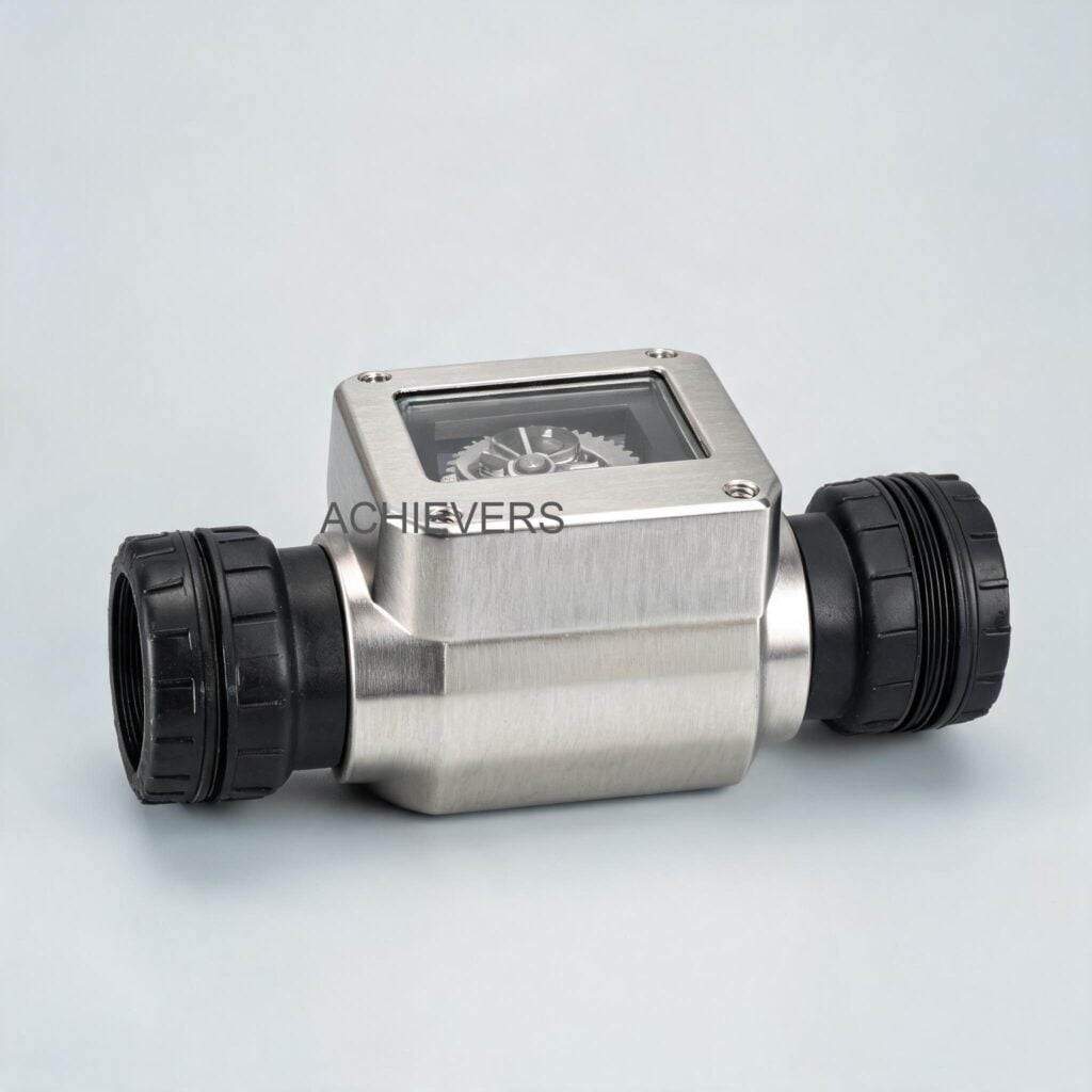
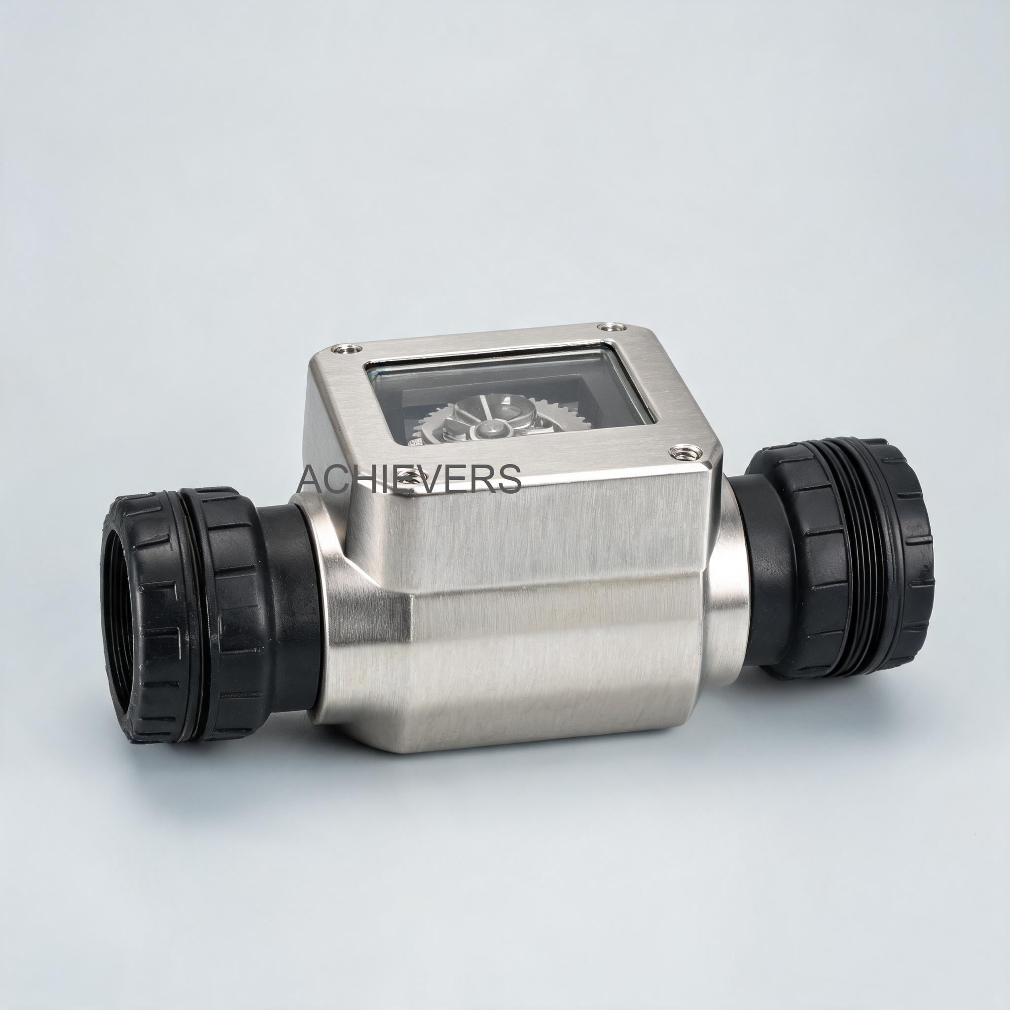
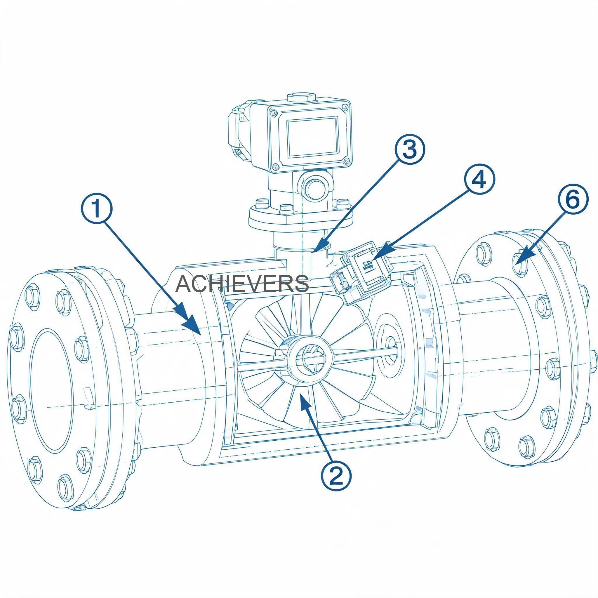
Before tearing down the system, it is vital to understand the basic working principle of the Diesel Flow Meter. Our meters operate on the positive displacement principle, specifically utilizing an oval gear mechanism. The measurement chamber contains two elliptical (oval) gears that mesh with each other.
When liquid enters from the inlet side, the fluid pressure causes the gears to rotate. The bottom gear acts as the driving gear, while the top acts as the driven gear. As they turn, a precise, fixed volume of liquid is trapped in the half-moon space between the gears and the outer shell, and then pushed toward the outlet. Because each rotation displaces an exact volume of liquid (four times the measurement room per full cycle), the flow rate is calculated simply by counting the gear rotations.
This design ensures an incredibly low pressure drop, making the Diesel Flow Meter highly suitable for gravity-fed dispensing systems common in rural Indian agricultural sites and elevated storage tanks in GIDC estates. Because it is a mechanical positive displacement meter, it is highly accurate and mostly unaffected by changes in fluid viscosity.
Here is a quick look at the technical specifications and operational limits of the standard models:
| Model Size | Min Flow Rate | Max Flow Rate | Accuracy | Repeatability | Max Viscosity | Max Pressure |
| — | — | — | — | — | — | — |
| 1 Inch | 20 LPM | 120 LPM | +/- 0.5% | 0.03% | 1000 CPS | 3.4 MPA |
| 1.5 Inch | 25 LPM | 250 LPM | +/- 0.5% | 0.03% | 1000 CPS | 1.8 MPA |
| 2 Inch | 30 LPM | 300 LPM | +/- 0.5% | 0.03% | 1000 CPS | 1.8 MPA |
2. Troubleshooting Matrix
When site operators report a fault, start with this rapid diagnostic matrix. It covers the most common symptoms seen across Indian construction sites, DG set yards, and transport hubs.
| Symptom | Likely Cause | Diagnosis Steps | Fix |
| — | — | — | — |
| Zero Reading on Display | Dead battery, loose wiring, or jammed oval gears. | Check battery voltage. Open the front cover to inspect the sensor wire. Manually check if gears turn. | Replace battery, tighten terminal connections, or clean debris from the measurement chamber. |
| Erratic or Fluctuating Reading | Air entrainment in the suction line or severe cavitation. | Look for bubbles in transparent hoses. Check suction side pipe joints for leaks. | Tighten all suction joints, apply fresh thread sealant, and bleed the line of trapped air. |
| High Pressure Drop Across Meter | Clogged upstream Y-strainer or fuel filter. | Isolate meter and open strainer housing. Inspect mesh for sludge or rust. | Clean or replace the strainer mesh. Ensure diesel from tankers settles before pumping. |
| Meter Running but No Fluid Passing | Vapor lock, empty tank, or broken gear shaft. | Check tank levels. Verify if pump is cavitating. Inspect internal gear shafts. | Refill tank, prime the system fully, or replace the internal oval gears if mechanically broken. |
| Grinding or Squealing Noise | Lack of lubrication (running dry) or solid particles in gears. | Stop flow immediately. Open the measuring chamber to check for scoring on gears. | Flush the chamber, remove the foreign particle, and ensure the pump is never run dry. |
| Display Fading or Blank | High ambient heat exposure or low power. | Check if installed in direct intense sunlight. Test battery output with a multimeter. | Install a sunshade over the meter and replace standard batteries with industrial-grade ones. |
| Leakage from Flange / Body | Blown O-ring or loose flange bolts. | Wipe meter clean and observe exactly where the drip originates under pressure. | Replace the O-ring (use Viton for diesel) and tighten flange bolts evenly in a star pattern. |
| Accuracy Drift (Under/Over reading) | Wear on gears, bypass leakage, or changed fluid viscosity. | Perform a calibration bucket test using a Legal Metrology certified standard measure. | Recalibrate the digital counter. If gears are heavily worn from abrasive fuel, replace them. |
| Sensor Output Signal Loss | Damaged reed switch or electrical interference. | Use a multimeter to check for pulse output while manually spinning gears. | Replace the magnetic sensor/reed switch and route signal cables away from high-voltage motor wires. |
| Valve Not Responding (If batched) | Solenoid failure due to voltage fluctuations. | Check incoming voltage. Inspect solenoid coil for burn marks. | Install a voltage stabilizer and replace the burnt solenoid coil. |
3. Step-by-Step Field Diagnosis Procedure
When facing complex issues like cavitation, air in the line, or severe pressure drop, guesswork will only waste time. Follow this standard 8-step field diagnosis procedure. You will need a digital multimeter, a standard wrench set, an Allen key set, a bucket, and a pressure gauge.
Step 1: Isolate and Secure the Area
Before opening any fuel line, shut off the power to your Fuel Transfer Pumps and close the isolation valves upstream and downstream of the meter. Follow standard PESO (Petroleum and Explosives Safety Organisation) safety guidelines to prevent fire hazards. Keep a spill kit handy.
Step 2: Verify the Gravity Feed Head (For Gravity Installations)
If the meter is installed on an elevated tank, ensure there is sufficient static head. A low fuel level in the tank reduces pressure, causing the flow rate to drop below the meter's minimum threshold (e.g., below 20 LPM for a 1-inch meter). This will result in inaccurate measurement. Refill the tank to increase head pressure.
Step 3: Inspect the Suction Side for Air Leaks
Air in the line is the number one cause of erratic readings. Oval gear meters measure volume, and they cannot tell the difference between a liter of diesel and a liter of air. Inspect all pipe joints, hose fittings, and valves between the storage tank and the pump. Look for weeping diesel; where diesel can leak out under pressure, air can be sucked in under vacuum.
Step 4: Check for Cavitation Conditions
Cavitation occurs when the suction pressure drops so low that the diesel temporarily vaporizes into gas bubbles, which then violently collapse inside the meter. This causes a rattling noise and rapid wear. Check if the suction hose is too long, too narrow, or crushed. In hot Indian summers, elevated temperatures make diesel more prone to cavitation if suction lines are restricted.
Step 5: Measure the Pressure Drop and Clean the Strainer
Indian diesel sourced from local tankers often contains dust, rust from old tanks, and sludge. An upstream Y-strainer is mandatory. If the flow feels sluggish, open the strainer. A completely clogged mesh forces the pump to work harder and drops the pressure at the meter inlet. Clean the mesh with a solvent and compressed air.
Step 6: Inspect the Oval Gears
If the meter is completely jammed, remove the front faceplate. Carefully extract the oval gears. Look for trapped debris like Teflon tape shreds, rust flakes, or small stones. Wash the gears in clean diesel. Check the gear shafts for excessive wear. If the gears rotate smoothly by hand, the mechanical section is fine.
Step 7: Test the Electronic Pulse and Display
If the gears turn but the display is dead, the issue is electronic. Use a multimeter to check the battery voltage. For external power models, check for 24V DC or 220V AC depending on the spec. Due to frequent voltage fluctuations in industrial estates, power surges can damage the PCB. Check the magnetic pickups (reed switches) to ensure they are registering the passing magnets on the gears.
Step 8: Perform a Calibration Verification Test
Once mechanical and electrical fixes are complete, perform a test draw. Dispense exactly 20 liters into a certified calibration can (as per the Legal Metrology Act). Compare the physical volume against the meter display. If there is a slight discrepancy (e.g., reading 20.2 liters), use the calibration factor adjustment on the digital display to dial it back to a perfect +/- 0.5% accuracy.
4. Installation and Setup Errors That Cause Ongoing Problems
Many troubleshooting calls we receive from across India stem directly from improper installation by local contractors. Positive displacement meters are robust, but they must be piped correctly. Here is a table of common installation errors, their symptoms, and how to correct them.
| Installation Error | Symptom | Correction |
| — | — | — |
| Omitting the upstream Y-strainer | Frequent jamming of gears and scored chamber walls. | Install a 100-micron or 60-mesh strainer directly upstream of the meter inlet. |
| Using excessive Teflon tape on threads | Gears jam immediately after commissioning. | Remove the meter, clean out the shredded Teflon tape from the gears, and use a liquid thread sealant instead. |
| Installing in areas of heavy vibration | Erratic digital display, cracked housing, or loose PCB connections. | Relocate the meter or isolate it using flexible braided stainless steel hoses on the inlet and outlet. |
| Reversing the flow direction | Meter does not register flow, or registers backward (if mechanical). | Check the directional arrow cast into the meter body and re-install it in the correct orientation. |
| Sizing the meter incorrectly (Too small) | Massive pressure drop, loud whining noise, premature gear wear. | Upgrade to a larger size (e.g., from 1-inch to 2-inch) to handle higher LPM without exceeding max pressure. |
| Rigid piping without thermal expansion relief | Flange leaks or body cracks during extreme summer heat. | Install thermal relief valves in the piping network to handle fluid expansion when exposed to the sun. |
5. Preventive Maintenance to Avoid Recurrence
Routine maintenance is the most cost-effective way to ensure your diesel fuel management system remains accurate and compliant with Indian accounting standards. In the context of Indian operations, you must account for high ambient dust (especially near mining or cement plants), high humidity during the monsoon, and inconsistent fuel quality.
Daily Checks:
Look for visible leaks around the flanges and the display housing. Check the sound of the operation; a healthy oval gear meter has a steady, quiet ticking sound. Any grinding means immediate shutdown is required.
Weekly Checks:
Drain the water from the bottom of your bulk diesel storage tanks. During the monsoon, condensation builds up inside storage tanks. While Oil Flow Meters and diesel meters can physically pass water, prolonged exposure to water causes the internal steel components to rust and the fuel to degrade.
Monthly Checks:
Open and clean the upstream strainer. Do not wait for the flow rate to drop. A clean strainer ensures a consistent pressure profile across the meter, maintaining the 0.03% repeatability spec. Also, check the calibration using a certified 20-liter or 50-liter proving measure. Under the Legal Metrology Act, commercial dispensing equipment must be periodically stamped and verified by local authorities. Keeping your meter perfectly calibrated ensures you easily pass these inspections.
In Simple Terms: Understanding Cavitation vs. Air in Line
Many operators confuse air in the line with cavitation.
Think of sucking a thick milkshake through a straw. If there is a crack in the side of the straw, you suck in outside air along with the milkshake. This is Air in the Line (usually caused by a loose pipe joint).
Now, imagine sucking that same thick milkshake through a very tiny, uncracked straw as hard as you can. The liquid can't flow fast enough, and the extreme vacuum actually boils the liquid into gas bubbles inside the straw. This is Cavitation (usually caused by clogged filters or hoses that are too narrow). Both cause your meter to over-read because it ends up measuring bubbles instead of pure diesel.
Market Context Note: For a budget-conscious plant manager, investing in preventive maintenance makes deep financial sense. A typical industrial-grade oval gear diesel flow meter in the Indian market ranges from ₹25,000 to ₹85,000 (plus 18% GST), depending on the line size and digital batching capabilities. Replacing a damaged measuring chamber due to a neglected ₹500 strainer is an avoidable capital expense. Furthermore, every 1% of inaccuracy on a 10,000-liter monthly diesel consumption costs a business roughly ₹9,000 a month in unaccounted fuel.
6. When to Call Service vs. Fix Yourself
Knowing your limits in the field is important. Most mechanical jams, strainer clogs, battery replacements, and air-bleeding tasks can be handled by an in-house fitter or maintenance technician within an hour. Recalibration of the digital display is also a field-level task, done via the front keypad.
However, you should contact the manufacturer or return the unit to our Ahmedabad facility for factory service if:
- The internal oval gears or the measuring chamber walls are deeply scratched or gouged. Polishing them in the field will alter the fixed volume of the chamber, permanently ruining the meter's accuracy.
- The digital PCB has short-circuited or shows burn marks from a voltage spike.
- The housing is cracked due to water freezing (rare in India, but possible in Himalayan regions) or severe mechanical impact.
- The meter requires an official re-certification and NABL/BIS traceable calibration certificate for an upcoming plant audit.
FAQ
Q: Why does my flow meter read more fuel than the tank actually received?
A: This is almost always caused by air passing through the meter. Positive displacement meters measure volume. If your pump sucks in air through a loose suction joint, or if the tank runs empty, the meter counts the air bubbles as diesel, leading to artificially high readings.
Q: Can I use this meter for both diesel and water?
A: No. While the mechanical principle can measure liquids, diesel flow meters rely on the lubricity of the fuel to keep the gears spinning smoothly. Pumping water will strip the lubrication, cause internal rusting, and quickly seize the gears.
Q: How often does the meter need to be calibrated under Indian regulations?
A: For internal accounting, we recommend verifying calibration every 3 to 6 months depending on usage. If the meter is used for commercial custody transfer (selling fuel), it must be verified and stamped annually by the local Legal Metrology Department.
Q: Does installing the meter vertically or horizontally matter?
A: Oval gear meters can be installed in horizontal or vertical pipelines. However, the internal gear shafts must always remain in a horizontal plane to prevent uneven wear. Always refer to the installation manual to ensure the dial face orientation is correct.
Q: My flow rate is very low because it is a gravity feed system. Will the meter still work?
A: Yes, oval gear meters have an exceptionally low pressure drop and are excellent for gravity feeds. However, ensure your flow rate meets the minimum requirement (e.g., 20 LPM for a 1-inch meter). If the flow drops below this, fluid may slip past the gears unmeasured, reducing accuracy.
Q: What should I do if the digital display goes blank during the monsoon?
A: Blank displays are usually due to dead batteries or moisture ingress into the electronic housing. Ensure the glass cover is tightened properly and the cable glands are sealed. If moisture has entered, dry the PCB gently and replace the batteries.
Q: Can I weld the flanges directly to my pipeline while the meter is attached?
A: Absolutely not. The extreme heat from welding will melt the internal O-rings, warp the measuring chamber, and destroy the electronics. Always tack-weld the counter-flanges, remove the meter, finish the welding, let the pipes cool, and then bolt the meter back into place.
If you are upgrading your facility, replacing outdated equipment, or struggling with ongoing diesel measurement issues at your plant, our technical team is ready to assist. Contact Lumen Instruments with your required flow rate, pipeline size, and site conditions, and we will guide you to a highly accurate, Make in India solution tailored to your budget and operational needs.