
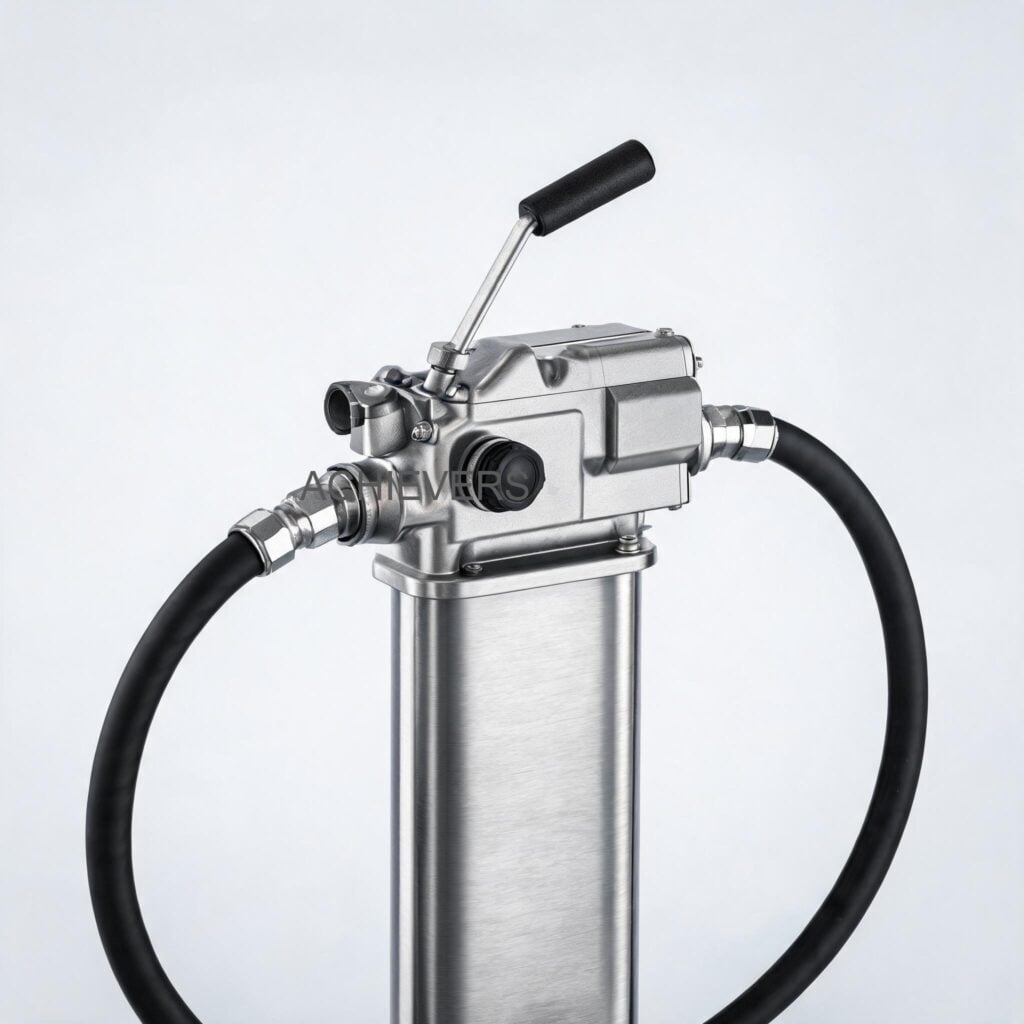
For industrial plants, construction yards, and transport fleets across India, the reliable flow of diesel and lubricants is the lifeblood of daily operations. Whether you are filling earth-moving machinery at a remote infrastructure site or maintaining backup diesel generator (DG) sets in a bustling GIDC (Gujarat Industrial Development Corporation) estate, equipment downtime is expensive. Unplanned failures of your Fuel Transfer Pumps not only halt production but can also lead to costly fuel spills, safety hazards, and emergency replacement costs.
Implementing a strict preventive maintenance checklist for fuel transfer pumps is the most effective way to ensure stable flow, reduce breakdowns, and extend the operational life of your equipment. A well-maintained pump consumes less electricity, operates with minimal noise, and delivers accurate flow rates consistently.
This comprehensive Fuel Transfer Pumps maintenance guide is designed for practical plant managers and business owners. We will cover critical wear components, outline a structured daily, monthly, and annual service schedule, and provide detailed step-by-step procedures to keep your equipment running smoothly in demanding Indian industrial environments.
1. Product Overview and Critical Wear Components
To understand how to maintain diesel fuel transfer pump for long life, you must first understand its mechanics. Lumen Instruments, a premier Fuel Transfer Pumps manufacturer and supplier based in Ahmedabad, Gujarat, engineers these pumps primarily as self-priming, rotary electric vane pumps.
Unlike standard centrifugal pumps, rotary vane pumps use a slotted rotor with sliding vanes that draw fluid into the pump chamber and push it out the discharge port. Because they are positive displacement pumps, they excel at generating high suction lift (up to 2-4 meters) and high flow rates (ranging from 20 L/min to 80 L/min). However, the friction of the moving vanes and the pressure dynamics of the fluids mean certain parts will naturally wear out over time.
Key Components That Require Monitoring
- Rotary Vanes: The vanes slide in and out of the rotor continuously. Over time, friction against the pump casing causes wear. If the fuel is contaminated with dirt or rust, this wear accelerates dramatically.
- Bypass Valve: All of our industrial Fuel Transfer Pumps are equipped with an integrated bypass valve. If the discharge nozzle is closed while the pump is running, the bypass valve opens internally to recirculate the fuel, preventing pressure buildup and motor burnout. If this valve gets stuck open due to debris, you will experience low flow.
- Inlet Strainer: Found in AC models like the CE-60A and CE-80B, the strainer acts as the first line of defense, catching large particulates before they enter the pumping chamber.
- Motor Brushes (DC Models): In 12V and 24V DC models (widely used on mobile fuel trucks and earth-moving equipment), the DC motor brushes wear down with operating hours and eventually require replacement.
- Seals and O-Rings: Rubber seals prevent leaks. Exposure to harsh chemicals, heat, or dry-running the pump can cause these seals to crack and fail.
Below is a technical summary of the Fuel Transfer Pumps configurations to help you identify the specific flow rates and power ratings of your equipment.
| Model | Operating Voltage | Flow Rate | Current / Power | Inlet/Outlet | Built-in Strainer / Bypass |
| — | — | — | — | — | — |
| CE-40DC | 12V / 24V DC | 40 L/min | 22A (12V) / 12A (24V) | 3/4 inch | Bypass Yes |
| CE-70-A-DC | 12V / 24V DC | 70 L/min | 4A (Check specific load) | 3/4 inch | Bypass Yes |
| CE-80-DC | 12V / 24V DC | 80 L/min | 44A (12V) / 21A (24V) | 1 inch | Bypass Yes |
| CE-60A | 220V AC | 20-60 L/min | 0.37 kW | 1 inch (Standard) | Bypass Yes / Strainer Yes |
| CE-80B | 220V AC | 20-70 L/min | 0.55 kW | 1 inch (Standard) | Bypass Yes / Strainer Yes |
In Simple Terms:
A Bypass Valve is a safety mechanism inside the pump. Imagine pinching a garden hose; the water pressure builds up rapidly. If you close the dispensing nozzle while a fuel pump is running, the pressure could destroy the motor. The bypass valve automatically opens to let the fuel circulate in a safe, continuous loop inside the pump until you open the nozzle again.
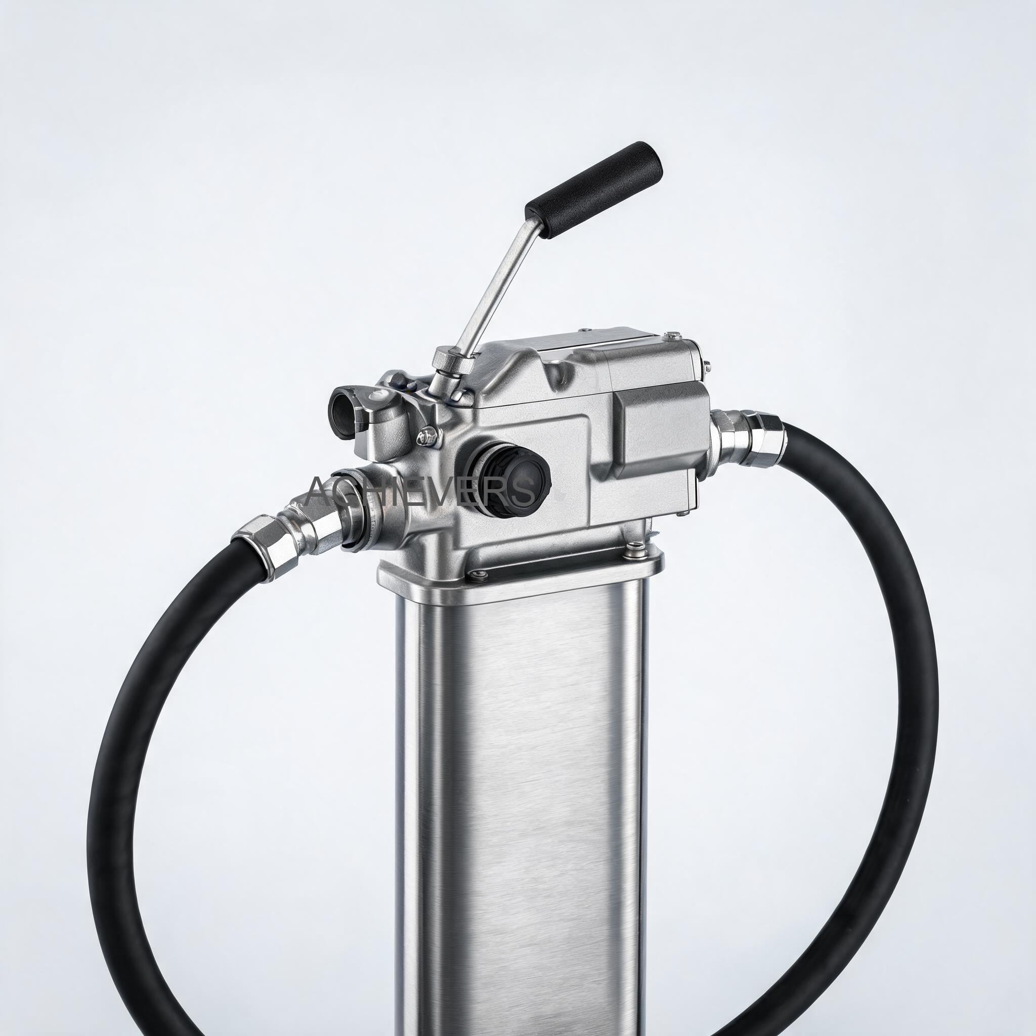
2. Preventive Maintenance Schedule
Creating a strict fuel transfer pump service schedule specifications document is mandatory for maintaining operations, especially in high-dust and high-heat environments typical of Indian industrial zones. Adhering to this maintenance schedule will drastically reduce the chances of catastrophic motor failure.
| Task | Frequency | Responsible | Est. Time | Notes |
| — | — | — | — | — |
| Visual Inspection for Leaks | Daily | Operator | 5 Mins | Check all hose connections, threaded joints, and the pump casing for diesel seepage. |
| Listen for Abnormal Noise | Daily | Operator | 2 Mins | Cavitation (sounds like marbles in the pump) indicates suction blockage or air leaks. |
| Inspect Power Cables | Daily | Operator | 2 Mins | Check 12V/24V battery clamps or 220V AC plugs for fraying or loose connections. |
| Check Suction Hoses | Weekly | Maintenance | 10 Mins | Look for collapsing hoses. A collapsed hose restricts flow and overheats the pump. |
| Clean Inlet Strainer/Filter | Weekly | Maintenance | 15 Mins | Absolutely critical in dusty environments or when pumping directly from metal barrels. |
| Test Bypass Valve Function | Monthly | Maintenance | 10 Mins | Run pump, close Fuel Nozzle, listen for smooth bypass operation (do not exceed 2 mins). |
| Check Motor Current Draw | Monthly | Electrician | 15 Mins | Use a multimeter. CE-80-DC on 12V should draw around 44A. High amps = internal friction. |
| Inspect DC Motor Brushes | Bi-Annually | Electrician | 30 Mins | For CE-40DC, CE-70-A-DC, CE-80-DC. Replace if worn down to less than 25% of original length. |
| Inspect Rotor and Vanes | Annually | Maintenance | 60 Mins | Open the pump head. Measure vane wear. Replace vanes if significantly worn or chipped. |
| Replace Shaft Seals | Annually | Maintenance | 45 Mins | Preventive replacement of O-rings and shaft seals prevents unexpected mid-season leaks. |
| Check System Calibration | Annually | Instrumentation | 30 Mins | If paired with a Diesel Flow Meter, verify output accuracy into a proven volumetric measure. |
| Clean Motor Cooling Fins | Annually | Maintenance | 15 Mins | Remove accumulated oil, dust, and grime from the motor exterior to ensure proper heat dissipation. |
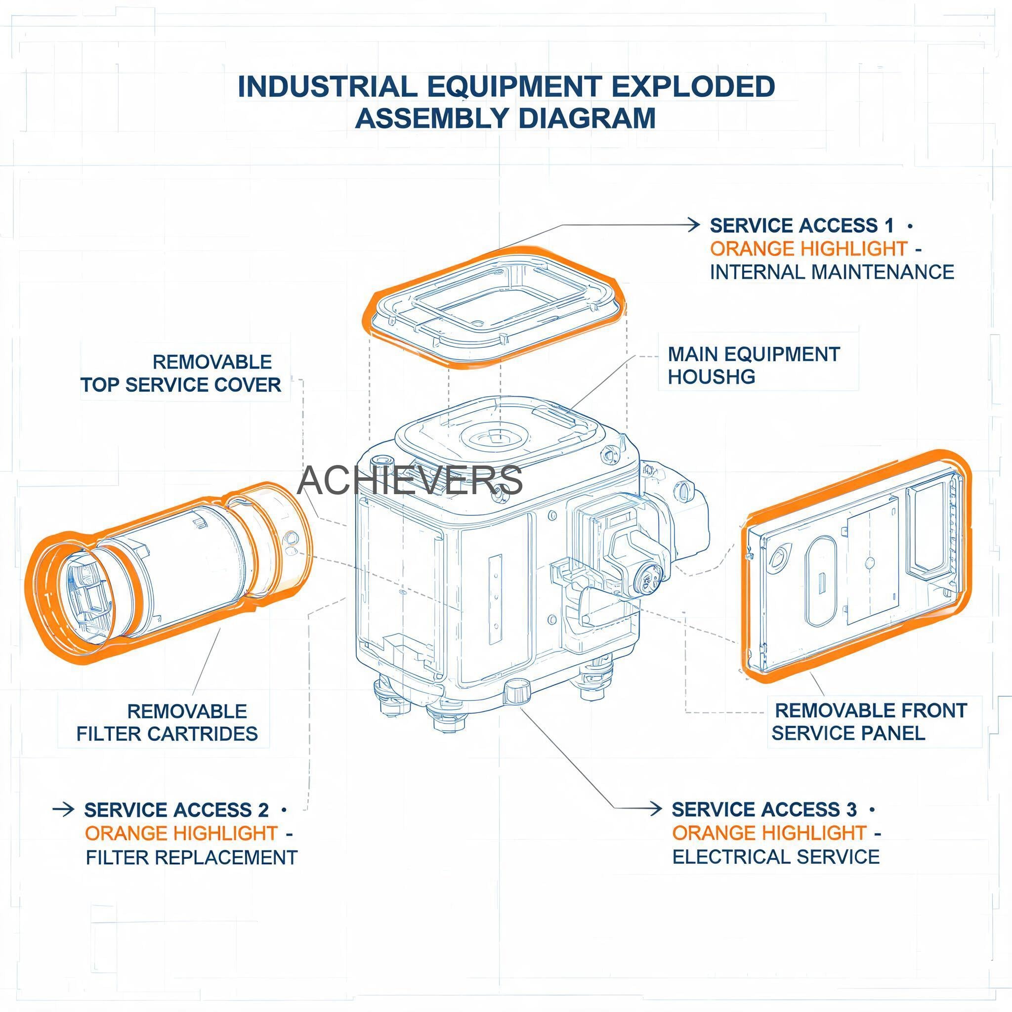
3. Step-by-Step Procedures for Key Tasks
Proper execution of maintenance tasks is just as important as the schedule itself. Incorrect reassembly can introduce air leaks, resulting in a pump that fails to prime. Below are two of the most critical maintenance procedures.
Procedure 1: Cleaning the Inlet Strainer (For AC Models CE-60A and CE-80B)
Inlet strainers protect the precision-machined vanes from rust, dirt, and debris. If you are operating Fuel Transfer Pumps for industrial use in India, where fuel is often stored in aging mild-steel tanks, the strainer is your primary defense against catastrophic wear.
- Disconnect Power: Completely isolate the pump from the electrical supply. Unplug the 220V AC connection and follow lock-out/tag-out (LOTO) procedures.
- Isolate the Fluid: Close the suction and discharge isolation valves (if installed) to prevent diesel from draining out of the pipes when you open the pump.
- Locate the Strainer Housing: On models like the CE-60A and CE-80B, the strainer is typically located at the inlet port, sometimes beneath a specific hex nut or inspection cover.
- Place a Catch Pan: Put a suitable chemical-resistant tray under the pump to catch residual diesel that will spill when the housing is opened.
- Remove the Strainer Cover: Using the appropriate wrench, loosen and remove the strainer access cap. Be careful not to damage or lose the sealing O-ring.
- Extract the Mesh Filter: Gently pull out the wire mesh strainer. Inspect it in a well-lit area.
- Clean the Mesh: Wash the strainer in a clean solvent (like clean diesel or kerosene). Use a soft-bristled nylon brush to dislodge trapped particles. Do not use compressed air at high pressure, as this can tear the fine wire mesh.
- Inspect and Reinstall: Hold the cleaned mesh up to the light to ensure no holes or tears exist. If it is damaged, replace it immediately.
- Reassemble: Seat the strainer back into its cavity, ensure the O-ring is perfectly positioned (apply a tiny drop of clean lube oil to the O-ring to prevent pinching), and tighten the access cap firmly.
- Prime and Test: Open the isolation valves, restore power, and run the pump for a few seconds to ensure it primes and there are no leaks around the cap.
Procedure 2: Vane Inspection and Bypass Valve Cleaning (For AC & DC Models)
Over time, carbon buildup from poor-quality fuel or minute debris can cause the sliding vanes to stick in the rotor slots, leading to a sudden drop in flow rate. Similarly, the bypass valve can become jammed open.
- Disconnect Power and Isolate Fluid: Ensure the machine is fully powered down (disconnect battery clamps for DC models like CE-80-DC) and fluid lines are valved off.
- Drain the Pump Chamber: Place a catch pan beneath the unit and disconnect the inlet and outlet hoses, allowing the residual fuel in the pump body to drain completely.
- Remove the Faceplate: Using an Allen key or socket wrench, carefully remove the bolts securing the pump faceplate. Keep pressure on the plate as you remove the last bolt, as there may be spring tension depending on the model design.
- Inspect the Faceplate O-ring: Remove the faceplate and immediately check the main sealing O-ring. If it is flattened, hard, or cracked, discard it for a replacement.
- Extract the Vanes: You will see the slotted rotor inside. Carefully slide out each vane (usually 5 to 7 vanes). Note their orientation—they must go back in the exact same way.
- Clean and Measure: Wipe down the rotor and vanes with a clean, lint-free cloth and solvent. Inspect the vanes for heavy scoring, chipping, or uneven wear. If they are significantly shorter than their original size or chipped, replace the entire set.
- Access the Bypass Valve: The bypass valve is typically located in a parallel chamber above or beside the main pumping chamber, held by a spring and a retaining plug. Unscrew the plug.
- Clean the Bypass Assembly: Pull out the bypass spring and the poppet valve. Clean the valve seat inside the pump body thoroughly. A piece of grit stuck here prevents the valve from closing, drastically reducing pump output pressure.
- Reassemble the Pump: Reinsert the bypass valve and spring, tightening the plug. Slide the vanes back into the rotor slots (ensure they slide freely with zero binding).
- Seal and Fasten: Place a new or perfectly clean O-ring on the faceplate, align it, and tighten the bolts in a crisscross (star) pattern to ensure even pressure and prevent warping.
4. On-Site Spare Parts to Stock
To truly minimize downtime, you must treat your fuel transfer pump like any other critical industrial asset. Relying on just-in-time shipping for spare parts can leave your machinery stranded. For Indian site conditions, where logistics to remote mining or construction sites can take days, we recommend maintaining a localized spares inventory.
| Part Description | Type | Recommended Qty | When to Replace |
| — | — | — | — |
| Rotary Vane Kit | Wear Part | 1 set per pump | When flow rate drops by >15% without blockage, or during annual inspection. |
| Main O-Ring / Seal Kit | Consumable | 2 sets per pump | Every time the pump faceplate is opened, or if external weeping occurs. |
| Inlet Strainer Mesh | Consumable | 2 units per pump | If torn during cleaning, or if heavily calcified/clogged with rust. |
| Bypass Valve Spring | Wear Part | 1 unit per pump | If the pump struggles to build pressure, indicating a weakened spring. |
| DC Motor Brushes | Wear Part | 1 set (for 12V/24V) | When brush length is <25%, or if the motor stutters/sparks excessively. |
| Power Switch | Electrical | 1 unit per pump | If the switch feels loose or fails to engage the motor consistently. |
5. Diagnosing Maintenance-Related Failures
Even with a robust preventive schedule, operating conditions can change rapidly. Below is a diagnostic guide to help your maintenance teams quickly identify the root cause of common issues.
| Failure Symptom | Most Likely Cause | Corrective Action |
| — | — | — |
| Motor runs, but no fuel is pumped (Fails to prime) | System is drawing air on the suction side, or the bypass valve is stuck open. | Check suction hose for cracks. Tighten inlet fittings. Clean the bypass valve assembly. |
| Flow rate is unusually low | Clogged inlet strainer or heavily worn rotary vanes. | Remove and clean the strainer mesh. If clear, open pump and inspect vanes for wear. |
| Pump is excessively noisy (Rattling/Grinding) | Cavitation due to suction restriction, or broken internal vane. | Ensure suction lift is within 2-4 meters limit. Clean strainer. Check for collapsed suction hose. |
| Motor runs very hot and trips breaker | Fluid too viscous, clogged discharge filter, or pump running in bypass too long. | Ensure fluid matches pump spec (Diesel/Kerosene). Never run in bypass (nozzle closed) for more than 2-3 minutes. |
| DC Pump motor does not start | Loose battery connections, burnt fuse, or worn-out carbon brushes. | Check battery voltage. Clean battery terminals. Inspect and replace motor brushes if needed. |
| Fuel leaking from the pump shaft | The mechanical shaft seal has failed due to wear or dry running. | Replace the mechanical shaft seal immediately to prevent diesel entering the electrical motor housing. |
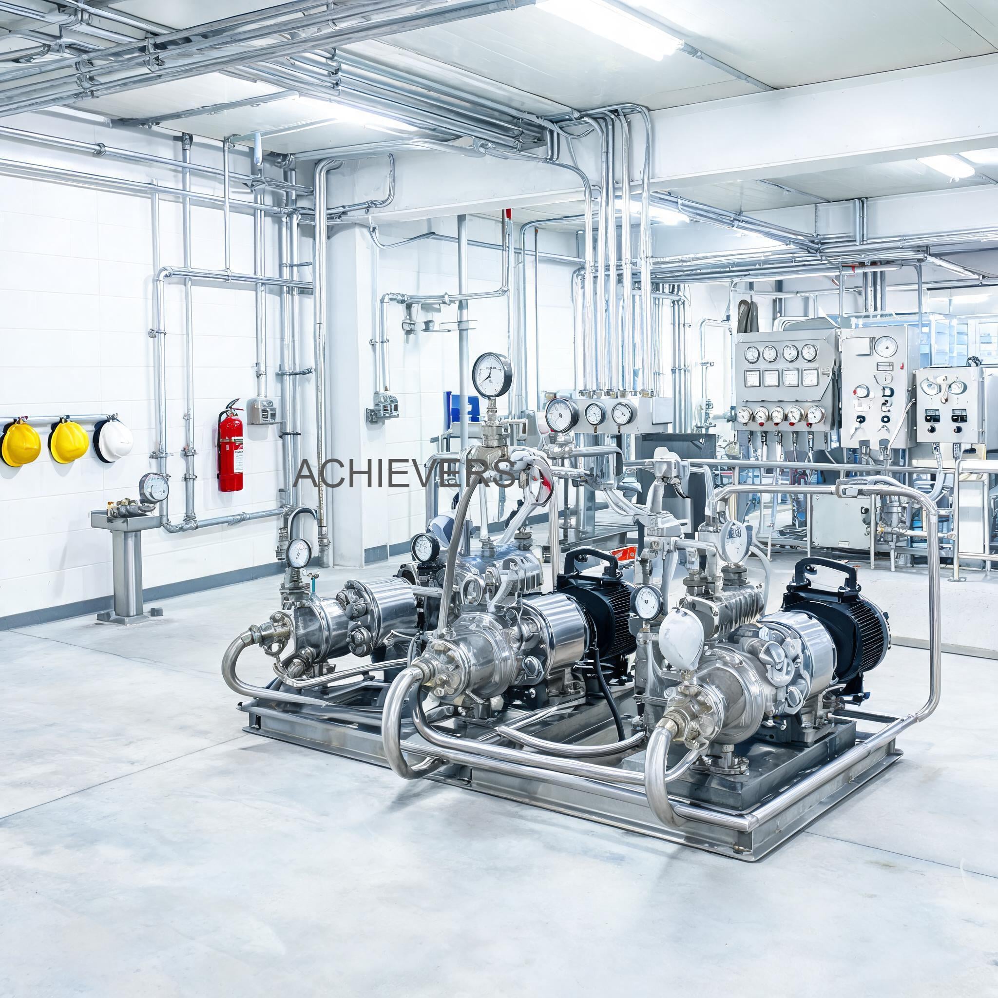
6. Extending Service Life in Indian Conditions
Operating industrial equipment in India presents unique challenges that global manuals often overlook. The Make in India initiative has bolstered domestic manufacturing standards, and Lumen Instruments builds robust products tailored to these realities. However, site-level care is paramount.
Managing Heat and Voltage Fluctuations
In states like Gujarat or Rajasthan, ambient summer temperatures frequently exceed 45°C. When a 220V AC pump (like the CE-60A or CE-80B) is left running in direct sunlight, the motor’s ability to cool itself diminishes. Always install a shade cover over stationary pumps. Furthermore, industrial estates (GIDCs) sometimes experience voltage drops. A 220V motor running on 180V will pull higher amperage to do the same work, generating excess heat. Ensure your control panels have adequate voltage stabilization or thermal overload relays.
Combating Dust and Contamination
Indian construction sites and mining operations are highly dusty. Dust settling on the pump is not just an aesthetic issue; if dust gets dragged into the suction hose during a barrel change, it becomes a grinding paste inside the pump housing. Always cap your hoses when not in use. Additionally, Indian market diesel from secondary transport tanks can sometimes contain water or rust scale. Investing in an external water-separator filter before the pump inlet will exponentially increase the life of your pump's internal vanes.
Cost-Conscious Maintenance
For budget-conscious Indian business owners, preventive maintenance is directly tied to profitability. The typical Indian market price range for high-quality industrial Fuel Transfer Pumps spans from ₹8,500 for standard DC units up to ₹25,000+ (GST-inclusive costs) for high-flow AC units with accessories. Replacing a ₹500 seal kit or a ₹200 strainer mesh annually protects a significant capital investment and guarantees your fleet stays fueled and operational.
FAQ
Q: How long can I safely run the pump with the dispensing nozzle closed?
A: You should never run the pump in bypass mode (nozzle closed) for more than 2 to 3 minutes. The fluid circulating inside the pump housing will rapidly heat up, which can damage the internal seals and overheat the motor.
Q: Can these pumps be used to transfer water or highly viscous gear oils?
A: No. These specific models (CE-40DC, CE-60A, etc.) are designed for diesel, kerosene, and light lube oils. Pumping water will cause the internal carbon/steel components to rust instantly. Pumping highly viscous oils will overload the motor.
Q: What is the maximum suction lift for the DC models?
A: Our rotary electric vane pumps, such as the CE-70-A-DC, are self-priming and can generally handle a suction lift of 2 to 4 meters. Exceeding this lift will cause cavitation and reduce the flow rate drastically.
Q: Why does my 12V DC pump keep blowing its in-line fuse?
A: A blowing fuse indicates the motor is drawing too much current. This is usually caused by a physical blockage inside the pump (like a jammed rotor), highly viscous fluid, or a collapsed suction hose forcing the motor to work harder.
Q: How often should I calibrate the fuel flow meter attached to the pump?
A: In standard industrial environments, we recommend verifying the calibration of your flow meter at least once a year, or whenever you notice discrepancies in fuel reconciliation.
Q: Are replacement parts easily available in the Indian market?
A: Yes. Because Lumen Instruments is an Ahmedabad-based manufacturer, all spare parts—including vanes, seals, bypass valves, and motor brushes—are strictly standardized and readily available for rapid dispatch across India.
Q: Is it necessary to install a foot valve on the suction hose?
A: While our pumps are self-priming, installing a foot valve with a built-in strainer at the bottom of your suction line is highly recommended. It keeps the line primed (reducing wear on startup) and acts as an excellent first filter against tank sludge.
To discuss the specific fluid handling needs of your site, order spare parts, or inquire about upgrading your current system, reach out to our engineering team today. Please provide your required flow capacity, application type, and on-site power availability, and we will help you select the most robust, cost-effective pumping solution for your business.