
Industrial facilities rely heavily on accurate fuel measurement to maintain operational budgets, prevent inventory shrinkage, and ensure smooth power generation. The cost of an unplanned flow meter failure extends far beyond the price of a replacement unit. When a primary measurement device drifts out of calibration or seizes due to particulate contamination, plant managers face costly downtime, inaccurate fuel billing, and disrupted production schedules. To prevent these costly scenarios, a rigorous, well-documented preventive maintenance schedule is absolutely essential.
Implementing an industrial diesel flow meter calibration and cleaning schedule is the most effective way to sustain high accuracy, repeatable performance, and a long service life. Whether you are operating a petrochemical plant, managing a heavy mining fleet, overseeing water treatment facility generators, or running an active production line in a manufacturing hub, routine maintenance transforms a delicate precision instrument into a rugged, long-lasting asset. This guide provides a comprehensive, step-by-step approach to maintaining your measurement infrastructure, ensuring that accuracy drift causes and maintenance challenges are addressed before they impact your bottom line.
1. Product Overview and Critical Wear Components
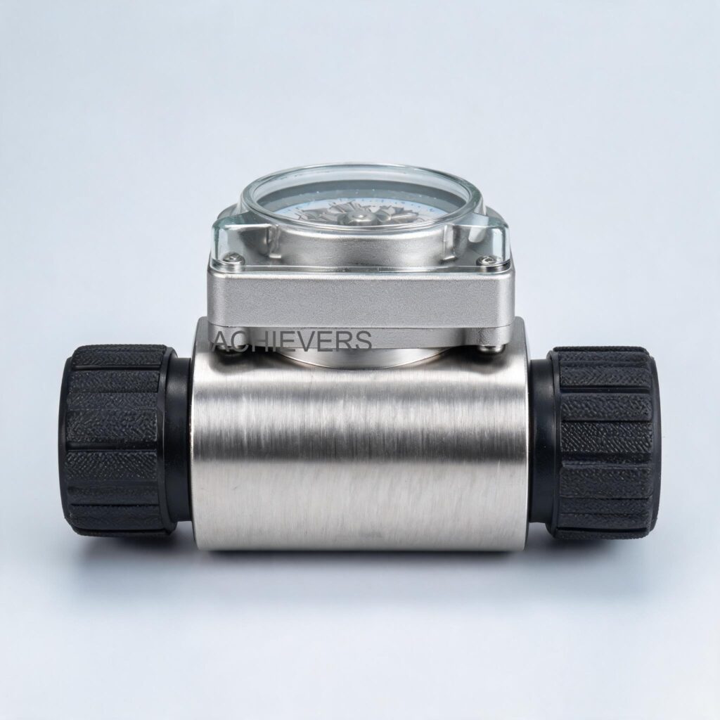
To properly maintain a Diesel Flow Meter, maintenance personnel must first understand its internal mechanics. This equipment utilizes a positive displacement mechanism, specifically incorporating an oval gear or oval rotor principle. This design provides a highly reliable and exceptionally accurate method of measuring fluid flow, offering strong repeatability across varying viscosity ranges.
The measurement chamber (or measuring room) houses two elliptical gears that mesh together. As fluid enters the inlet side, the pressure forces the gears to rotate. The bottom gear acts as the driving gear, while the upper gear functions as the driven gear. During rotation, a precise, fixed volume of liquid is trapped in the crescent-shaped cavity between the gears and the outer housing. With each full rotation, this trapped liquid is pushed toward the outlet. Because the volume displaced per revolution is strictly constant, the meter simply counts the rotations to determine the exact total volume of fluid passed.
Because the system relies on physical contact and tight tolerances between the oval gears and the housing walls, specific internal components are subject to mechanical wear. The bearings supporting the gear shafts, the gears themselves, and the elastomeric O-rings sealing the measurement chamber are the primary wear parts. Understanding the technical specifications of your Diesel Flow Meter helps dictate the maintenance intervals. For instance, operating near the maximum pressure or flow limits will accelerate bearing wear.
Below is the technical specification data for standard models, which highlights the operating parameters that must be respected to minimize unnecessary wear:
| Technical Parameter | 1" Size Model | 1.5" Size Model | 2" Size Model |
| — | — | — | — |
| Min Flow Rate | 20 LPM | 25 LPM | 30 LPM |
| Max Flow Rate | 120 LPM | 250 LPM | 300 LPM |
| Accuracy | +/- 0.5% | +/- 0.5% | +/- 0.5% |
| Repeatability | 0.03% | 0.03% | 0.03% |
| Max Viscosity | 1000 CPS | 1000 CPS | 1000 CPS |
| Max Pressure | 3.4 MPA | 1.8 MPA | 1.8 MPA |
When integrating these meters into larger Diesel Dispensing networks, ensuring that upstream pumps do not exceed the stated maximum pressure (e.g., 3.4 MPA for the 1-inch model) is the first line of preventative maintenance.

2. Preventive Maintenance Schedule
A robust diesel flow meter preventive maintenance checklist must be divided into daily, weekly, monthly, and annual intervals. Assigning clear responsibilities and estimating time requirements ensures that these checks are actually performed rather than ignored during busy production shifts. Consistency in executing this schedule directly correlates to the longevity and sustained +/- 0.5% accuracy of the unit.
| Task Description | Frequency | Responsible Role | Est. Time | Important Notes |
| — | — | — | — | — |
| Visual Inspection | Daily | Plant Operator | 5 mins | Check for external weeping or pooling around flanges and the mechanical register/digital display. |
| Display Verification | Daily | Plant Operator | 2 mins | Ensure the digital display is active or the mechanical ticket printer is advancing without hesitation. |
| Acoustic Check | Weekly | Maintenance Tech | 5 mins | Listen for grinding, clicking, or irregular noises indicating gear wear or particulate ingress. |
| Strainer / Filter Cleaning | Monthly | Maintenance Tech | 30 mins | Isolate the line and clean the upstream Y-strainer to prevent gear blockage. |
| Leak and Seal Check | Monthly | Maintenance Tech | 15 mins | Wipe down all flange connections and housing joints; inspect for hairline cracks in seals. |
| Wiring & Terminal Check | Quarterly | Electrical Tech | 20 mins | For digital units, inspect power/signal terminals for corrosion or loose connections due to vibration. |
| Flow Rate Verification | Quarterly | Plant Engineer | 45 mins | Compare meter output against a known calibrated volume or master meter to check for early drift. |
| Calibration & Proving | Bi-Annually | Metrology Team | 2 hours | Perform formal proving using a volumetric test measure; adjust the calibration factor if needed. |
| Measurement Room Clean | Annually | Maintenance Lead | 3 hours | Full teardown of the measurement chamber to remove sludge, varnish, and inspect gear mesh tolerances. |
| O-Ring & Bearing Replace | Annually | Maintenance Lead | 3 hours | Preventative replacement of primary seals and gear bearings, regardless of visual condition. |
When adhering to this schedule, facilities can expect their meters to easily outlast their standard warranty periods while providing the exceptional repeatability (0.03%) required for strict inventory audits.
3. Step-by-Step Procedures for Key Tasks
While routine visual checks are straightforward, internal maintenance requires strict adherence to engineering best practices. Below are two critical, detailed procedures that form the backbone of your maintenance program.
Procedure 1: Upstream Strainer and Filter Cleaning
Because positive displacement meters have extremely tight clearances between the oval gears and the chamber walls, hard particulates like rust, sand, or weld slag will cause catastrophic jamming. Cleaning the upstream strainer is non-negotiable.
- Initiate Lockout/Tagout (LOTO): Shut down all upstream Fuel Transfer Pumps and electronically lock out the control panels to prevent accidental activation.
- Isolate the Metering Line: Close the primary inlet and outlet isolation valves located before and after the Diesel Flow Meter and its strainer assembly.
- Depressurize the System: Safely bleed off any trapped line pressure using the designated bleed valve or vent plug. Collect any residual fluid in an approved spill-containment tray.
- Access the Strainer Basket: Using the appropriate wrenches, carefully loosen and remove the bolts securing the Y-strainer or filter housing cap.
- Remove and Inspect the Mesh: Extract the internal stainless steel mesh screen. Inspect it under bright lighting for tears, stretched wires, or collapsed sections. If damaged, it must be discarded, not cleaned.
- Clean the Mesh: Use a dedicated parts washer with a compatible, non-corrosive solvent to dissolve sludge. Use compressed air (blowing from the inside out) to dislodge trapped hard particles.
- Replace Housing Seals: Remove the old O-ring or gasket from the strainer cap. Clean the seating groove thoroughly, lubricate a new O-ring with a compatible light oil, and seat it carefully.
- Reassemble and Test: Reinstall the mesh and bolt down the cap using a star-pattern torque sequence. Slowly open the inlet valve to re-pressurize, checking for leaks before returning the system to normal operation.
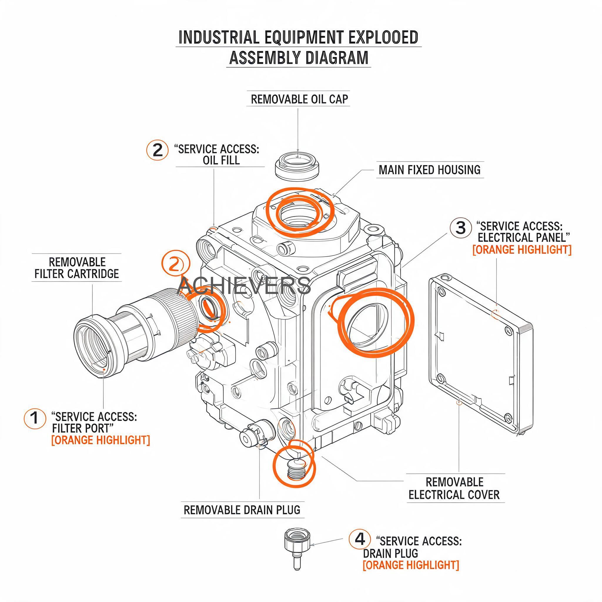
Procedure 2: Measurement Chamber Cleaning and Seal Replacement
Over time, diesel fuel can leave behind a sticky varnish, or microscopic debris can accumulate, leading to accuracy drift causes and maintenance challenges. Annual cleaning of the measuring room is highly recommended.
- System Isolation and Draining: Follow the standard LOTO procedure, isolate the valves, and drain the meter completely. Ensure the work area is well-ventilated and free of ignition sources (complying with ATEX/ISO safety standards).
- Remove the Meter from the Line: Unbolt the inlet and outlet flanges. Carefully lift the meter out of the pipeline and move it to a clean, well-lit workbench.
- Detach the Register Unit: Carefully unscrew and remove the mechanical register or digital display head. Set it aside in a safe, dry location to protect its delicate gears or electronics.
- Open the Measurement Chamber: Remove the heavy bolts securing the front cover plate of the meter body. Tap the cover gently with a rubber mallet if the seal is stuck; do not use metal screwdrivers to pry it open, as this will scratch the machined sealing surfaces.
- Extract the Oval Gears: Note the exact orientation and timing marks on the elliptical gears. Carefully slide the driving gear and the driven gear off their respective shafts.
- Clean Components Thoroughly: Wash the gears, the chamber walls, and the shafts using an industrial solvent. Inspect the gear teeth for pitting, scoring, or uneven wear. Check the shaft bearings for excessive play.
- Replace Internal Seals: Remove the large main cover O-ring and the smaller shaft seals. Discard them. Thoroughly clean the O-ring grooves to remove any hardened residue, then install fresh, lubricated O-rings.
- Reassembly and Calibration: Slide the gears back onto their shafts, ensuring the timing marks align perfectly for smooth meshing. Reattach the cover plate and torque the bolts to the manufacturer's specifications. Reinstall the meter in the pipeline, reattach the register, and run a mandatory calibration proving test before trusting the measurement data.
4. On-Site Spare Parts to Stock
Supply chain delays can turn a minor three-hour maintenance task into a three-week operational shutdown. To avoid this, an experienced Diesel Flow Meter supplier for manufacturers will always recommend keeping a localized inventory of critical spare parts. Having the right consumable parts immediately available guarantees maximum uptime.
Below is the recommended spare parts inventory matrix:
| Part Description | Component Type | Recommended Stock Qty | When to Replace |
| — | — | — | — |
| Main Cover O-Ring | Elastomeric Seal | 3 – 5 per meter size | Annually, or whenever the measurement chamber is opened. |
| Shaft Bearings/Bushes | Mechanical Wear Part | 2 sets | Every 2-3 years, or if acoustic checks reveal grinding noises. |
| Strainer Mesh Basket | Filtration Component | 2 per meter | If the mesh is torn, crushed, or heavily fouled beyond cleaning. |
| Oval Gear Set | Precision Measurement | 1 set per meter size | If teeth are scored, chipped, or if severe accuracy drift cannot be calibrated out. |
| Register Coupling | Mechanical Linkage | 2 units | If the meter is turning but the display is failing to register flow. |
| Flange Gaskets | Plumbing Seal | 5 sets | Whenever the meter is removed from the pipeline for bench maintenance. |
5. Diagnosing Maintenance-Related Failures
Even with a strong preventive maintenance schedule, unexpected operating conditions can trigger performance issues. Understanding how to diagnose symptoms quickly will save hours of blind troubleshooting. The following diagnostic matrix maps common failure symptoms to the maintenance tasks that were likely missed, providing immediate corrective actions.
| Failure Symptom | Likely Missed Maintenance Task | Corrective Action Required |
| — | — | — |
| Reduced flow rate / High pressure drop | Monthly strainer/filter cleaning | Isolate line, open Y-strainer, clean or replace the fouled mesh basket. |
| Meter registers flow but no fluid passes | Valve inspection; System bleed | Check for a ruptured bypass valve or clear massive air entrainment in the line. |
| Fluid passes but meter does not register | Internal gear inspection | Gears are jammed by debris or the register coupling pin has sheared. Teardown required. |
| Sudden drop in measurement accuracy | Bi-annual calibration; Gear wear check | Perform volumetric proving. If calibration fails, inspect oval gears for severe wear. |
| Leakage around the meter housing | Annual O-ring and seal replacement | Tighten cover bolts. If weeping continues, replace the main cover O-ring. |
| Digital display flickers or dies | Quarterly wiring/terminal check | Inspect power supply, replace internal battery, or clean corroded terminal contacts. |
By using this troubleshooting guide, plant operators can communicate precisely with their engineering teams, reducing downtime and ensuring that the appropriate spare parts are mobilized immediately.
6. Extending Service Life in Indian Conditions
While the fundamental engineering of positive displacement meters is universal, local operating environments heavily influence maintenance needs. Facilities operating across global markets—and particularly those managing plants in India—must account for specific regional challenges. High ambient temperatures, seasonal humidity, voltage fluctuations, and dusty industrial environments demand a more aggressive approach to maintenance.
Operating a plant in an Indian industrial hub, such as a GIDC (Gujarat Industrial Development Corporation) estate, means exposing equipment to severe summer temperatures that can exceed 45°C. This high heat lowers the viscosity of diesel fuel and can accelerate the degradation of standard rubber O-rings. Ensuring that your flow meters are equipped with high-temperature, chemical-resistant seals (like Viton or PTFE) is crucial. Furthermore, the intense humidity during the monsoon season poses a significant threat to the electronic components of a Digital Diesel Flow Meter. Moisture ingress can corrode the printed circuit boards of the digital display or damage the paper feed mechanisms in a Print Flow Meter with Ticket Printer. Silica gel packets should be placed inside electrical enclosures and replaced quarterly.
Power quality is another critical factor. Industrial sectors frequently experience power surges and voltage dips. If you are using digital meters connected to a central PLC or building automation system, installing localized surge protectors and high-quality UPS backups is essential to prevent electronic component failure and data loss during power transitions.
In Simple Terms:
Think of your precision flow meter like the engine of a high-performance truck. If you don't change the oil filter regularly, abrasive dirt gets into the engine block and destroys the cylinders. Similarly, if you don't clean your flow meter's strainer, rust and dirt from your fuel tanks will get inside the measuring chamber, scratch the oval gears, and permanently ruin the meter's accuracy. A simple 30-minute cleaning job saves you from buying a whole new meter.
From a procurement perspective, budget-conscious buyers must look beyond the initial sticker price. The typical Indian market price range for an industrial-grade diesel meter can vary widely based on size, flow capacity (from 120 LPM up to 300 LPM), and whether it features mechanical or digital registers. When evaluating the budget, plant managers must account for the GST-inclusive cost (typically 18% for industrial measurement equipment in India) alongside the cost of commissioning and calibration.
Purchasing from a local manufacturer aligned with the Make in India initiative—such as a Diesel Flow Meter supplier based in Ahmedabad, Gujarat—provides significant long-term advantages. It ensures compliance with relevant Indian industry standards, aligns with BIS (Bureau of Indian Standards) quality expectations, and most importantly, guarantees that critical spare parts are available within days rather than the weeks required for imported alternatives. When a plant avoids exorbitant import duties and shipping delays for a simple set of replacement oval gears, the total cost of ownership plummets.
FAQ
Q: How often should I calibrate my industrial diesel flow meter?
A: For high-volume applications or custody transfer operations, calibration should be verified every six months using a certified volumetric proving tank. For standard internal inventory tracking, an annual calibration check is usually sufficient, provided the meter passes its routine visual and acoustic inspections.
Q: Why is the meter ticking or grinding during operation?
A: A grinding or ticking noise is a strong indicator that hard particulate matter has bypassed the strainer and is caught between the oval gears and the measuring room wall. The system should be shut down immediately, and the measuring chamber must be opened, cleaned, and inspected for scoring.
Q: Can I use this meter for fluids other than diesel?
A: Yes, these positive displacement meters are highly versatile. According to the manufacturer specifications, they are suitable for diesel, kerosene, petrol, MTO, and biodiesel, handling a maximum viscosity of up to 1000 CPS. However, they are strictly forbidden for measuring highly corrosive chemicals unless specialized wetted materials are used.
Q: What causes the accuracy of the meter to drift over time?
A: Accuracy drift is primarily caused by mechanical wear on the oval gear teeth or the shaft bearings. As the physical tolerances between the gears and the housing increase due to friction, small amounts of fluid "slip" past the gears without being measured, causing the meter to under-register the total volume.
Q: Does temperature affect the meter's reading?
A: Because positive displacement meters measure actual volumetric flow, significant temperature fluctuations that cause the diesel fuel to expand or contract can affect the mass-to-volume ratio. However, the mechanical accuracy of the meter itself (+/- 0.5%) remains highly stable across its designed temperature range.
Q: Why is my mechanical ticket printer jamming?
A: Ticket printer jams are often caused by excessive ambient humidity (especially during monsoon seasons) which causes the ticket paper to swell, or by heavy dust accumulation on the mechanical gear trains. Regular cleaning with compressed air and keeping the cover securely latched will prevent this.
Q: How do I choose between a 1-inch, 1.5-inch, and 2-inch meter?
A: Selection must be based strictly on your system's maximum flow rate and pressure capabilities. A 1-inch meter handles up to 120 LPM at 3.4 MPA, while a 2-inch meter can process up to 300 LPM but operates safely at a lower maximum pressure of 1.8 MPA. Never force high volumes through a small meter to save upfront costs, as this will destroy the internal components.
To optimize your fuel measurement infrastructure, secure reliable spare parts, or discuss the specific flow capacity, operating pressure, and site conditions of your facility, we invite you to contact our technical team today. Let Lumen Instruments help you select and maintain the perfect Diesel Flow Meter to guarantee accuracy and efficiency for your operations.